Power sensor tour
R&S
®
NRP Series
28Getting Started 1419.0170.02 ─ 16
4.1 RF connector
The RF connector is used for connecting the power sensor to a device under test
(DUT) or a signal generator. See Chapter 3.4, "Connecting to a DUT",
on page 13.
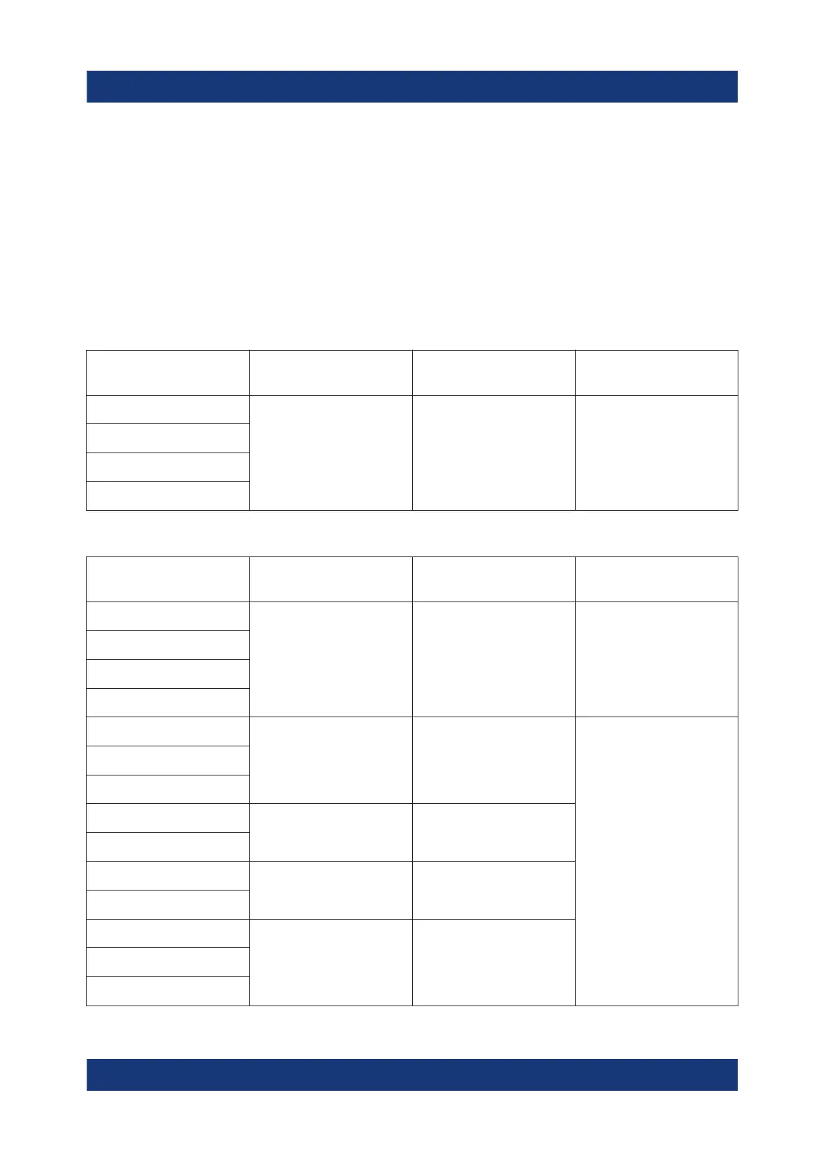
For maximum measurement accuracy, tighten the RF connector using a torque
wrench with a nominal torque as specified in the following table.
Table 4-1: R&S
NRPxxA(N) RF connector characteristics
Power sensor Male connector Matching female
connector
Tightening torque
R&S NRP6A
N N
1.36 Nm (12'' lbs)
R&S NRP6AN
R&S NRP18A
R&S NRP18AN
Table 4-2: R&S
NRPxxS(N) RF connector characteristics
Power sensor Male connector Matching female
connector
Tightening torque
R&S NRP8S
N N
1.36 Nm (12'' lbs)
R&S NRP8SN
R&S NRP18S
R&S NRP18SN
R&S NRP33S
3.50 mm
3.50 mm/ 2.92 mm/
SMA
0.90 Nm (8'' lbs)
R&S NRP33SN
R&S NRP33SN-V
R&S NRP40S
2.92 mm
3.50 mm/ 2.92 mm/
SMA
R&S NRP40SN
R&S NRP50S
2.4 mm 2.4 mm/ 1.85 mm
R&S NRP50SN
R&S NRP67S
1.85 mm 1.85 mmR&S NRP67SN
R&S NRP67SN-V
RF connector

 Loading...

