Power sensor tour
R&S
®
NRP Series
27Getting Started 1419.0170.02 ─ 16
4 Power sensor tour
This chapter provides an overview of the available connectors and LEDs of the
power sensor.
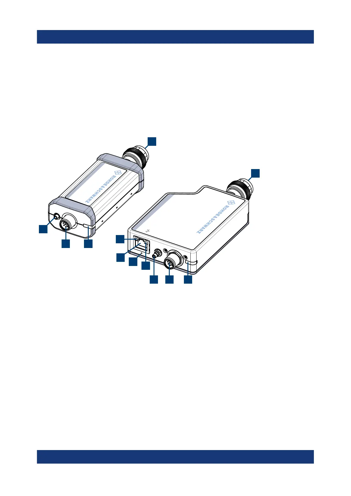
In Figure 4-1, the USB power sensor is shown on the left, the LAN power sensor
is shown on the right.
HOST
INTERFACE
IN:
3 V or 5 V logic
OUT: min. 2 V into 50
Ω
max. 5.3 V
TRIG2
I/0
PoE
SMART SENSOR TECHNOLOGY
NRP
SMART SENSOR TECHNOLOGY
NRP
1
1
4
2
2
3
34
8
5
6
7
Figure 4-1: R&S
NRP series power sensors (example)
1 = RF connector, see Chapter 4.1, "RF connector", on page 28
2 = Status LED, see Chapter 4.2, "Status information", on page 30
3 = Host interface connector, see Chapter 4.3, "Host interface", on page 30
4 = Trigger I/O connector, see Chapter 4.4, "Trigger I/O connector", on page 30
5 = Network status LED, see "Network status LED" on page 31
6 = LAN reset button, see "LAN reset button" on page 31
7 = LAN connector, see Chapter 4.5, "LAN PoE interface", on page 31
8 = Power over Ethernet status LED, see "Power over Ethernet status LED" on page 31

 Loading...

