Power sensor tour
R&S
®
NRP Series
29Getting Started 1419.0170.02 ─ 16
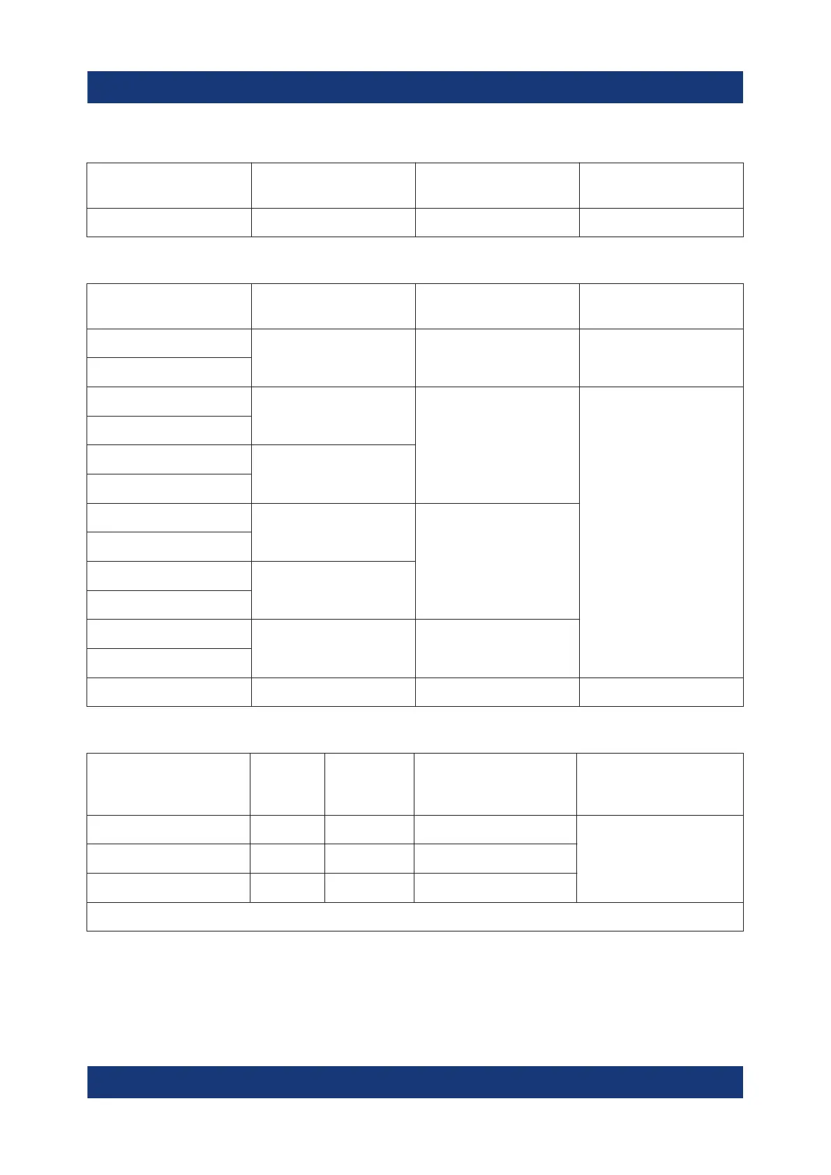
Table 4-3: R&S NRP18S
‑
xx RF connector characteristics
Power sensor Male connector Matching female
connector
Tightening torque
R&S NRP18S
N N
1.36 Nm (12'' lbs)
Table 4-4: R&S
NRPxxT(N) RF connector characteristics
Power sensor Male connector Matching female
connector
Tightening torque
R&S NRP18T
N N
1.36 Nm (12'' lbs)
R&S NRP18TN
R&S NRP33T
3.50 mm
3.50 mm/ 2.92 mm/
SMA
0.90 Nm (8'' lbs)
R&S NRP33TN
R&S NRP40T
2.92 mm
R&S NRP40TN
R&S NRP50T
2.4 mm
2.4 mm/ 1.85 mm
R&S NRP50TN
R&S NRP67T
1.85 mm
R&S NRP67TN
R&S NRP90T
1.35 mm 1.35 mm
R&S NRP90TN
R&S NRP110T 1.0 mm 1.0 mm 0.23 Nm (2'' lbs)
Table 4-5: R&S
NRPxxTWG RF connector characteristics
Power sensor Male
connec-
tor
Matching
female
connector
Frequency range Tightening torque*
R&S NRP75TWG
WR-15 WR-15
50 GHz to 75 GHz
0.58 Nm (5'' lbs)R&S NRP90TWG
WR-12 WR-12
60 GHz to 90 GHz
R&S NRP110TWG
WR-10 WR-10
75 GHz to 110 GHz
* Use the torque wrench for waveguide flanges, R&S ZCTW, part number 1175.2014.02.
RF connector

 Loading...

