36
INSTALLATION
Check the appliance is electrically safe and gas sound when you have nished.
ArtNo.215-0026 - Handle gaskets fixed
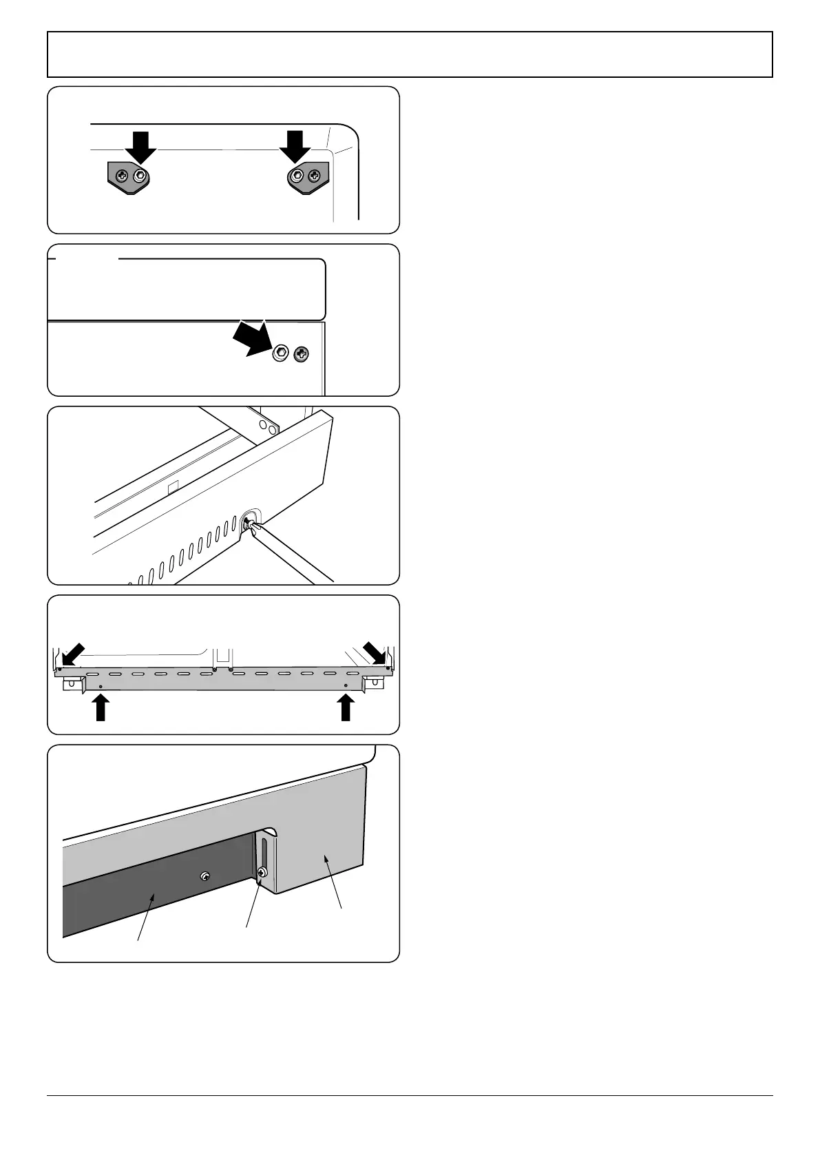
ArtNo.350-0012 - Securing the plinth
Art No 215-0028 - Handrail fascia fixings
ArtNo.350-0010 - Fitting the plinth 1 (Kitchener)
ArtNo.350-0011 - Fitting the plinth 2 (Kitchener)
Outer plinth
Outer plinth xing screw
Inner plinth
Fig. 10.15
Fig. 10.16
Final Fitting
Fitting the Handles and Handrail (Classic Deluxe)
Remove the 4mm Allen screws from the doors (Fig. 10.15).
Fit the door handles and secure using the 4 mm screws.
The handles should be above the xings.
Remove the 4 mm Allen screws from the top corners of the
fascia (Fig. 10.16). Fit the front handrail in position and
secure using the 4mm screws.
Fitting the 1-piece Plinth
(Professional +)
Loosen the 3 screws along the front bottom edge of the
cooker. Hook the central keyhole over the central screw. Twist
and t each end keyhole over their respective screws. Tighten
the xing screws (Fig. 10.17).
Fitting the 2-piece Plinth (Classic and Kitchener)
Fit the inner plinth to the bottom front of the cooker using
the 4 screws provided (Fig. 10.18).
Fit the outer plinth (2 screws, 1 each end) to the inner plinth.
The height of the outer plinth can be adjusted by sliding it up
or down via the slotted hole (Fig. 10.19).
Fitting the Splashback (Classic)
The cooker can be installed with or without the supplied
splashback.
To t the splashback, rst remove the two 3 mm xing screws
and nuts on the rear of the grill ue. Hold the splashback in
position and ret the screws and nuts to secure.
Customer Care
Installer: Please complete your details in this guide, inform
the user how to operate the cooker and hand over the
instructions.
Thank you.
Fig. 10.17
Fig. 10.18
Fig. 10.19