a
b
e
f
c
d
1
2
g/y
bk
r
b
b
b
g/y
or
br
w
b
r
y
r
y
r
bk
b
v
br
bk
br
r
b
gr
w
b
b
b
b
br
b
b
b
b
b
b
br
v
r
r
v
br
r
br
y
y
r
v
or
v
v
v
br
v
r
r
br
v
r
r
v
br
gr
v
r
r
r
r
b
v
b
r
b
r
bk
v
r
v
r
g/y
b
b
w
y
r
A1
C
B1
B2
B4
D2
G
D1
D3
D4
F1
I
F2
H
A3
A2
A4
B3
J
L
I
I
K
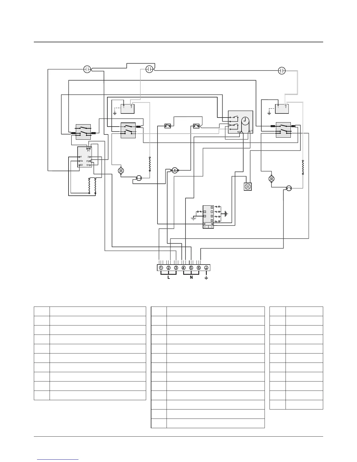
Key
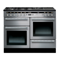
The connections shown in the circuit diagram are for single-phase. The ratings are for 230 V 50 Hz.
Classic
Code Colour
b Blue
br Brown
bk Black
or Orange
r Red
v Violet
w White
y Yellow
g/y Green/yellow
gr Grey
Code Description
A1 Grill Front Switch
A2 Grill Energy Regulator
A3 Grill Elements -LH
A4 Grill Elements - RH
B1 Left-Hand Oven Thermostat
B2 Left Hand Oven Front Switch
B3 Left Hand Oven Fan Element
B4 Left Hand Oven Fan
C Clock / Timer
Code Description
D1 Right - Hand Oven Thermostat
D2 Right - Hand Oven Front Switch
D3 Right- Hand Oven Element
D4 Right - Hand Oven Fan
F1 Left - Hand Oven Thermal Preset
F2 Right - Hand Oven Thermal Preset
G Left Hand Oven Light
H Cooling Fan
I Indicator Neon
J Ignition Switch
K Oven Light Switch
L Spark Generator