13
BALANCER OVERVIEW
This machine is a two-plane, microprocessor-based computer
balancer. Any imbalance in a wheel, either static or dynamic,
is detected into two correction planes (the inner and outer)
where corrective weights can be applied. Pressing the F
button selects either DYNAMIC or STATIC modes and
pressing the ALU button selects the ALU modes, all of which
change the location of the planes.
Determining the Planes
When the distance gauge is pulled out and held against
the wheel flange, the distance measurement shown on the
pull out slide refers to the DISTANCE OFFSET
MEASUREMENT. This measurement tells the computer
the location of the INNER plane of the wheel for Dynamic
and/or Alloy balancing.
By using the WHEEL CALIPERS and / or the OUTER
GAUGE-ARM, the wheel width or the WIDTH MEASUREMENT
tells the computer the location of the OUTER plane of the wheel
for Dynamic and/or Alloy balancing.
The wheel diameter will be referred in this manual as the
DIAMETER MEASUREMENT. This is the diameter of the
wheel at the weight location. You can determine the diameter
of the wheel / tire on the tire sidewall to determine the wheel
diameter. Or you can use the calipers. This tells the computer
how far from the center of the hub the weights will be applied.
Balancing a Wheel
When a wheel is spun, the balancer detects any imbalance
present. The computer calculates the weight needed to
correct the imbalance and the location for weight application.
The weight required to correct the imbalance is displayed on
the control panel, and the weight positioning lights assist the
operator in positioning the weight application location at
top-dead-center. Weight displays and positioning lights are
provided for both inner and outer planes of the wheel.
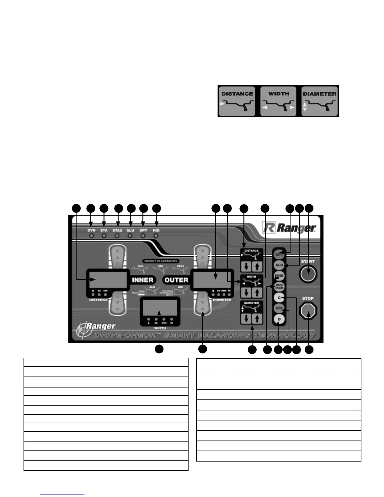
CONTROL PANEL AND DISPLAY
1. Weight reading or information display window. INNER
2. DYN mode indicator.
3. STATIC 1 mode indicator.
4. STATIC 2 mode indicator.
5. ALU mode indicator.
6. OPT mode indicator.
7. HID mode indicator.
8. Weight reading or information display window. OUTER
9. Rim WIDTH setting keys.
10. Wheel OFFSET setting keys.
11. FINE button (<5g.) for identifying remaining weight.
12. OPT button for optimizing the match of tire and rim.
13. Selector key for DYNAMIC, ALLOY and ALLOY-S modes.
14. START button for activating spin cycle.
15. STOP Button for stopping spin cycle.
16. C button for selecting G / OZ.
17. STA button for selecting DYNAMIC, STATIC & STATIC-2 modes.
18. D button for running the balancers self-test.
19. Toggle between MM and INCH settings.
20. Rim DIAMETER setting keys.
21. Target indicator LEDs.
22. WIDTH reading or information display window.
1 2 7 8 9 10 113
4
5
6
1819
20
2122
12 13
14
151617