SERIES 2000 INSTALLATION, OPERATION AND SERVICE MANUAL
8
SECTION 5: SPECIFICATIONS
Estimated weight table applies to both upright and
horizontal units of the same model. See Page 9,
Ta b l e 3 .
Unless otherwise requested, all direct-fired air
handlers are set-up to accept an external static
pressure (ESP) of 1 in wc (2.5 mbar). The external
static pressure is the sum of all accessories and any
attached ductwork. See Page 11, Table 5 and Table 6
for static pressure accessories. If more external static
pressure is required, this needs to be requested with
the order as required motor horsepower (HP) may
increase from the specifications given on Page 10,
Ta b l e 4 .
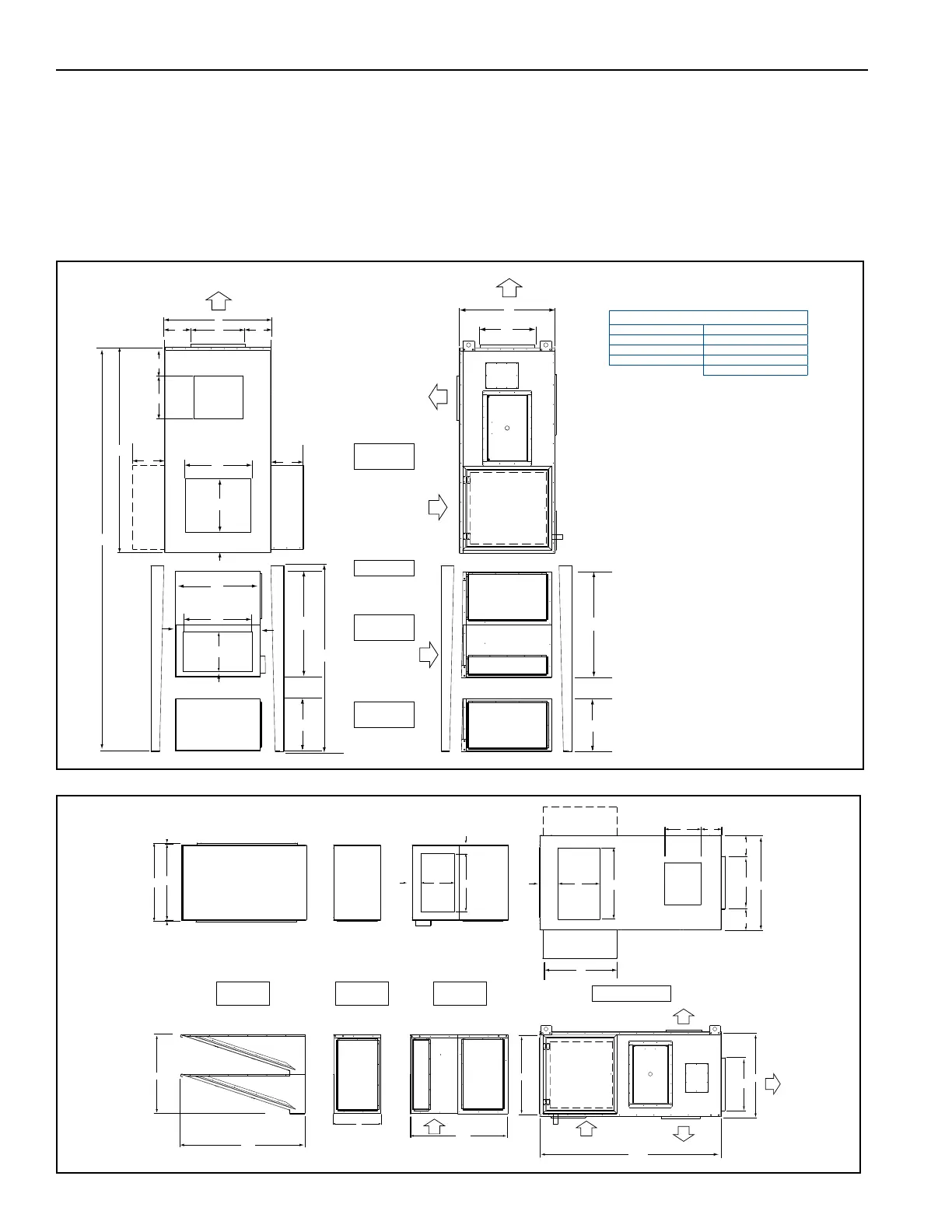
FIGURE 1: Vertical Dimensions
FIGURE 2: Horizontal Dimensions
Fan/Burner
Section
Filter Mix Box
(Optional)
Filter Section
(Optional)
Legs
P
GC
ED
BD
BR
DT1
CE
A
F
C
ED
F
B
G
U
H
H
V1
CC
RA
M
J
E
D
BD
BR
BR
G
U
LL
V2
T2
HH
Z
K
HH
Z
J
LC
LC
RC
(Shown)
(Backside)
RC
LEGEND
BD = Bottom Discharge OA = Outside Air
CE = Control Enclosure RA = Return Air (Optional)
GC = Gas Connection TD = Top Discharge
ED = End Discharge RC = Right Hand Controls
LC = Left Hand Controls
Y
Filter Mix Box
(Optional)
Filter Section
(Optional)
Inlet Hood
(Optional)
Fan/Burner Section
AA
TD or BD
RA
V1 U
H
DE
C
F
F
A
GG
G
H
FF
FF
D
P
ED
BD
B
DD
GC
HH
Z
W
BB
CE
TD
T
V2 U
H
G
H
BR
BR
BR
LC
RC
RC
LC
(Shown)
(Backside)