SECTION 9: UPRIGHT I NSTALLATION
21
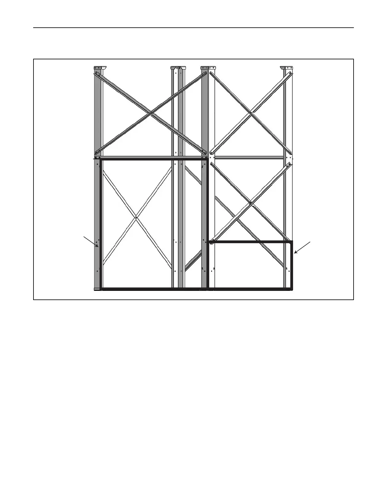
Step 5: Attach remaining support braces taking note of the support location to proper orient for your air
handler's configuration. See Page 21, Figure 10.
FIGURE 10: Step 5
9.2 Upright Installation
To attach the legs to a concrete slab, it must be
secured with the use of studs, embedded in the
concrete. Four 5/8" studs (minimum) must be
installed in the slab, one for each corner of the stand.
The stand has four 3/4" (19.0 mm) holes drilled
through the stand pads. Fasten the stand to the slab
with four 5/8" hex nuts and lock washers (provided by
others).
9.3 Attaching Air Handler
Once the stand is secured to a concrete slab, the air
handler may be placed on the stand. If the unit has a
filter section, the filter section must be installed in the
leg assembly prior to placing the air handler, see
Page XX, Section 10.3. Prior to lifting the air handler,
apply the foam tape and remove the attaching
hardware as described below. The ½"
(12.7 mm) thick double-sided urethane foam tape
(provided by others) must be applied to the top edge
of the stand. Remove the lifting lugs and re-install the
hardware. See Page 22, Figure 11. Lift the air
handler on to the legs. See Page 12, Section 6.1 for
safe lifting practices. Once the air handler is placed
on the legs, sec
ure it with the provided attaching
hardware recommended torque settings. After
placing the air handler on the legs, seams between
the mounting legs and the air handler must be
properly caulked (caulk provided by others).
NOTE: If using a filter section with an upright air
handler and legs, the filter section must be set into
the legs before the air handler is mounted on the
legs. The 1/2" (12.7 cm) thick double-sided urethane
foam tape should be applied between the legs and
the filter section. See Page 23, Section 10.3.
Control Side
Filter Access
Return
Air