SECTION 18: DIRECT FIRED BURNER
59
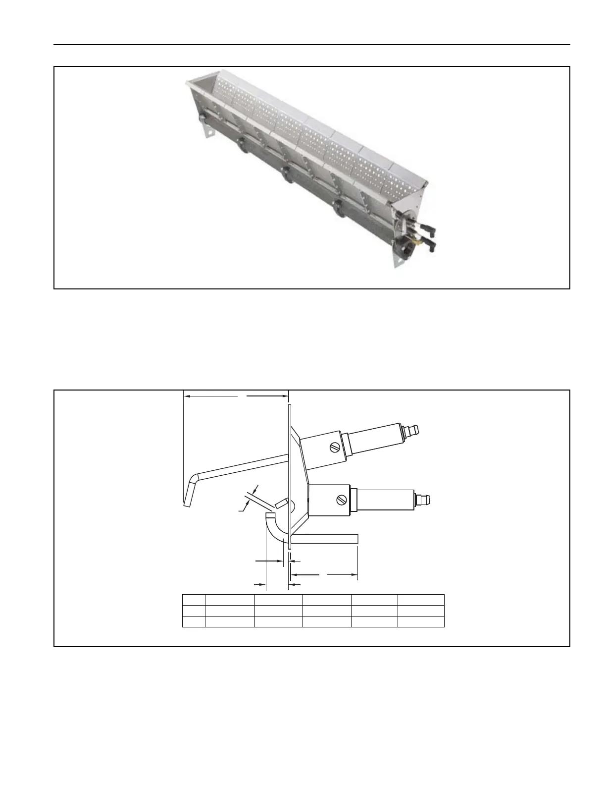
FIGURE 28: HMA-2A Burner
18.1 Direct Fired Burner Ignition
The burner that is used in the Rapid Engineering
LLC unit is equipped with a pilot assembly. The pilot
assembly consists of a pilot gas tube, spark
electrode or rod and a flame rod with grounding
assembly. For proper ignition the spark rod must be
adjusted correctly. A high voltage arc is generated
between the spark rod and the pilot gas tube. The
gas flowing out the ports in the pilot gas tube is
ignited by this arc. The arc will be a brilliant electric
blue in color. See Page 59, Figure 28.
FIGURE 29: Spark Rod Dimensions
The gas supplied to the pilot gas tube should be 3 1/
2" wc for natural gas and between 9 to 11" wc for
propane or LP. The difference between the two fuels
is that a restricting orifice is installed in the propane
or LP pilot gas tube. The pilot assembly can be used
on propane or LP without an orifice, if this is the case
then the pressure for LP is 2.0"w.c. Ignition will take
place with the introduction of gas to the pilot gas
tube. The pilot flame will be mostly blue in color with
streaks of yellow. The flame size will be roughly 2" in
diameter. The flame must be steady and consistent
in size.
B
C
E
D
A
WARNING: the ignition system on the air handler generates between 6,000 to 10,000 volts.
ABCDE
in 2.940 0.125 0.125 1.881 0.633
cm 7.468 0.318 0.318 4.778 1.608