SECTION 7: ROOF
15
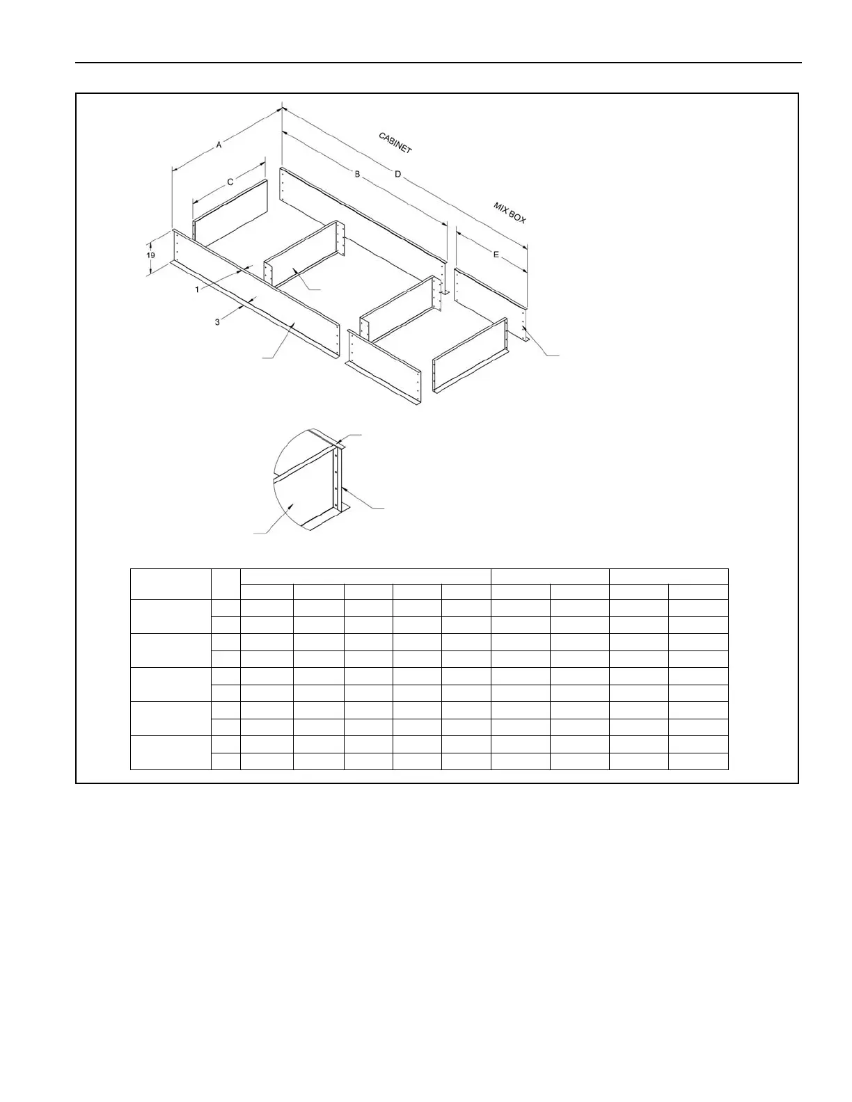
FIGURE 5: Roof Curb Assembly
NOTE:
*Blower and Burner Section
**Blower, Burner and Mixbox
*** Split sides and Cross Brace for Model 2030
• Curb is shipped unassembled.
• A and B are outside dimensions for the top of the curb.
• Curb material is 14 gauge galvanized steel.
• Nuts and bolts (3/8" x 1") are furnished.
• Caulk all joints before assembling. (Caulk provided by others)
Caulk required for outside perimeter
of roof curb at bolted joints.
Top Mounting Flange
Side Panel
End Panel
(Inlet or Discharge)
***Side panels are split
***Cross Brace
Model
Dimensions Weight* Weight**
ABCDElbskg lbs kg
2005
(in)
25.9 78.2 22.9 131.7 53.5 96 43 140 63
(cm)
65.8 198.6 58.2 334.5 135.9
2010
(in)
39.3 102.5 36.3 155.5 51.4 133 60 179 81
(cm)
99.8 260.3 96.8 395.1 128.1
2010B
(in)
47 93 42.1 143.2 47.9 130 59 173 78
(cm)
119.4 236.2 111.6 363.8 119.2
2020
(in)
53.5 113.6 48.9 183 69 153 69 216 97
(cm)
135.9 288.5 128.8 464.8 175.3
2030
(in)
76.6 151.8 73.1 215.4 64.6 210 94 268 121
(cm)
194.6 385.6 190.3 547.1 161.5