PAGE 20/36 | Installation manual | 016-8000-014EN | Rev. A1
STEERING SYSTEM INSTALLATION | CRX + SC1 | RAVEN EUROPE GENERIC
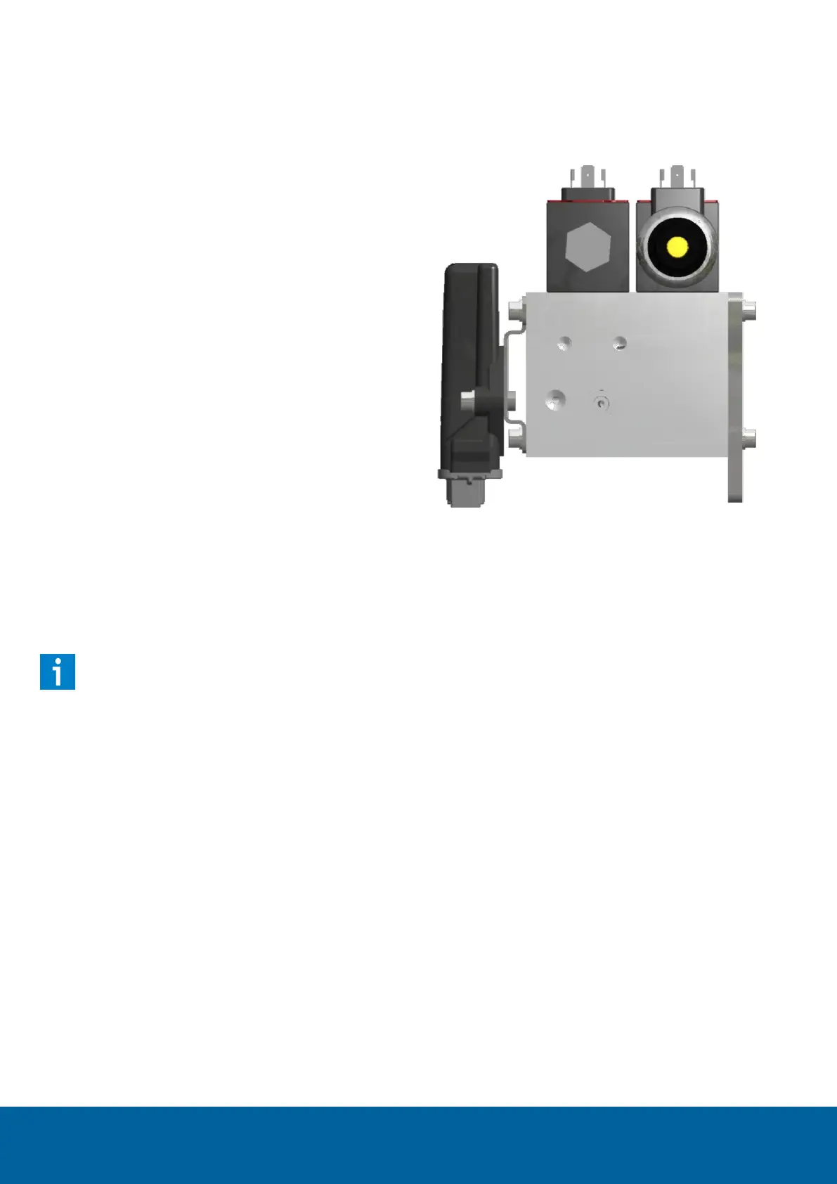
1.3.7 MOUNTING AND CONNECTING THE
HYDRAULIC DRIVE UNIT
The Hydraulic Drive Unit bracket can be mounted to
the manifold. The Hydraulic Drive Unit can then be
fitted to the manifold bracket (Figure 14).
Important notes when mounting the Unit:
Mount the Hydraulic Drive Unit with
connectors directed downwards to prevent the
ingress of water.
Do not mount the Hydraulic Drive Unit too
close to parts which have a high temperature
(for example, the exhaust system of the
tractor).
Connect the DIN connectors marked "Left" and “Right”
to the proportional valve. Connect the DIN connector
marked "Lock" to the shut-off valve. Connect the 4-pin
Phoenix M12 connector to the pressure sensor of the
manifold.
Please note!:
The torque of the pressure sensor in the
manifold V3 is 30 Nm. It is not necessary to
check this at delivery of an assembled
manifold. However, make sure, when replacing
the pressure sensor, that it is tightened with
the correct torque.
FIGURE 14 SIDE VIEW OF THE HYDRAULIC DRIVE
UNIT TO THE MANIFOLD

 Loading...


