5
P/N 016-5032-114 Rev. A 33
CAB COMPONENT INSTALLATION
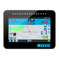
FIGURE 14. Open Port of Side Console Cover
8. Identify an open port on the machine’s side console cover.
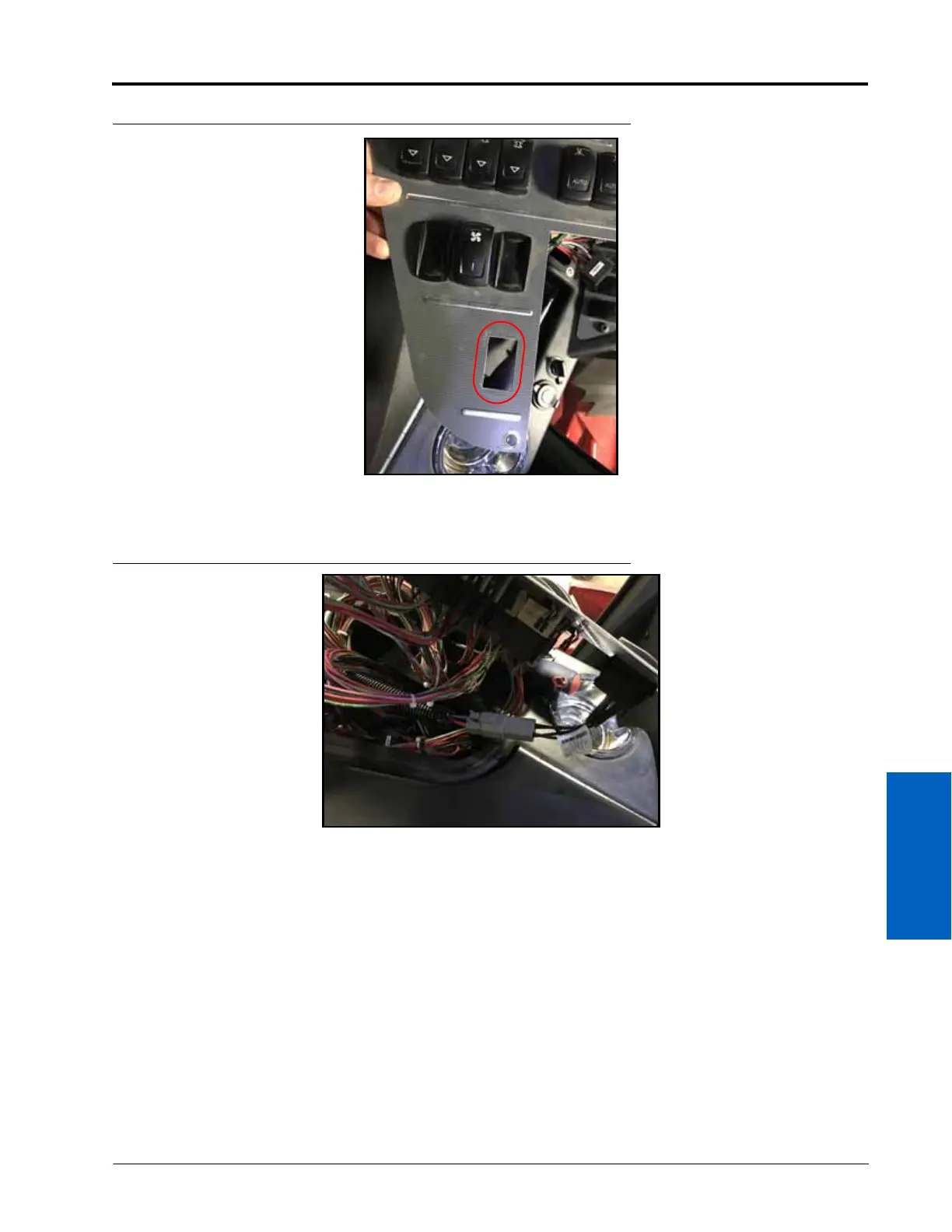
FIGURE 15. STEERING LOCKOUT SWITCH Connector
9. Position the master switch (P/N 063-0173-961) over the open port in the side console cover, feeding the switch
cable through the opening.
10. Connect the STEERING LOCKOUT SWITCH connector of the HDU harness cable (P/N 115-4010-063) to the
master switch connector.

 Loading...