51
APPENDIX 7
IMPREGNATION MODULE INSTALLATION
1. PLUMBING IMPREGNATION MODULE
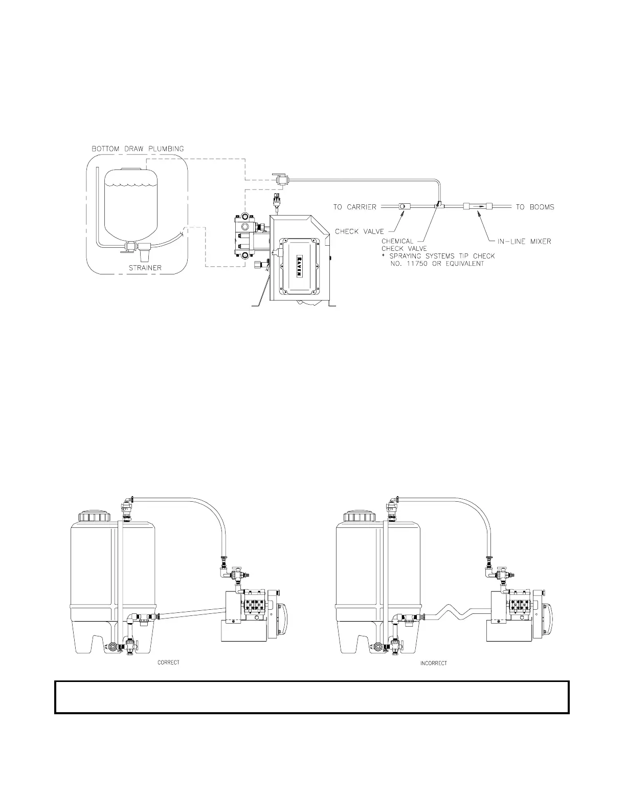
IMPORTANT: Inlet hose must have gradual upward slope to pump inlet fitting
with no dips or sags.
FIGURE 21
FIGURE 20
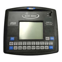
1) Plumb the Pressure Relief Valve (PRV), Flow Meter, Control Valve, Carrier Check Valve, Product
Check Valve, and In-Line Mixer just ahead of the Boom On/Off Valves as shown in Figure 4.
2) Mount Injection Module close to the Boom On/Off Valves to minimize amount of product in tubing.
3) Plumb three way valve on output line of Injection Module (See Figure 20). Plumb recirculation line
from three way valve to Product supply tank using 3/8 inch [10mm] tubing. Plumb injection line from
three way valve to product check valve using 3/8 inch [10 mm] tubing (For low volume modules) or
1/2 inch [13 mm] tubing (for high volume modules). Product Check Valve and tubing not furnished.
4) Plumb inlet hose from product tank as shown in Figure 21.
5) See "ADJUSTING PUMP SETTING".
6) See "MOUNTING THE CONSOLE AND CABLING" for installation of Control Console.
 Loading...