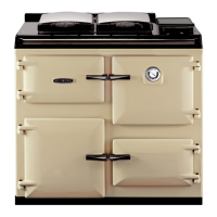
SEE FIG. 25
Follow instructions in sections BURNER ACCESS, Steps
1 to 3 and BURNER REMOVAL.
1. Isolate electric supply.
2. Remove 3-pin plug.
3. Remove solenoid plug.
4. Disconnect oil pipe.
5. Undo 2 screws and remove snorkel.
6. Remove 4 countersunk screws from fan case and split
the case.
7. Remove grub screw and withdraw fan.
8. Remove 4 countersunk screws and remove fan motor
from case.
9. Remove 3 socket head screws and withdraw pump.
10.Re-assemble in reverse order.
NOTE: Ensure that gaskets and seals are in place and in
good condition.
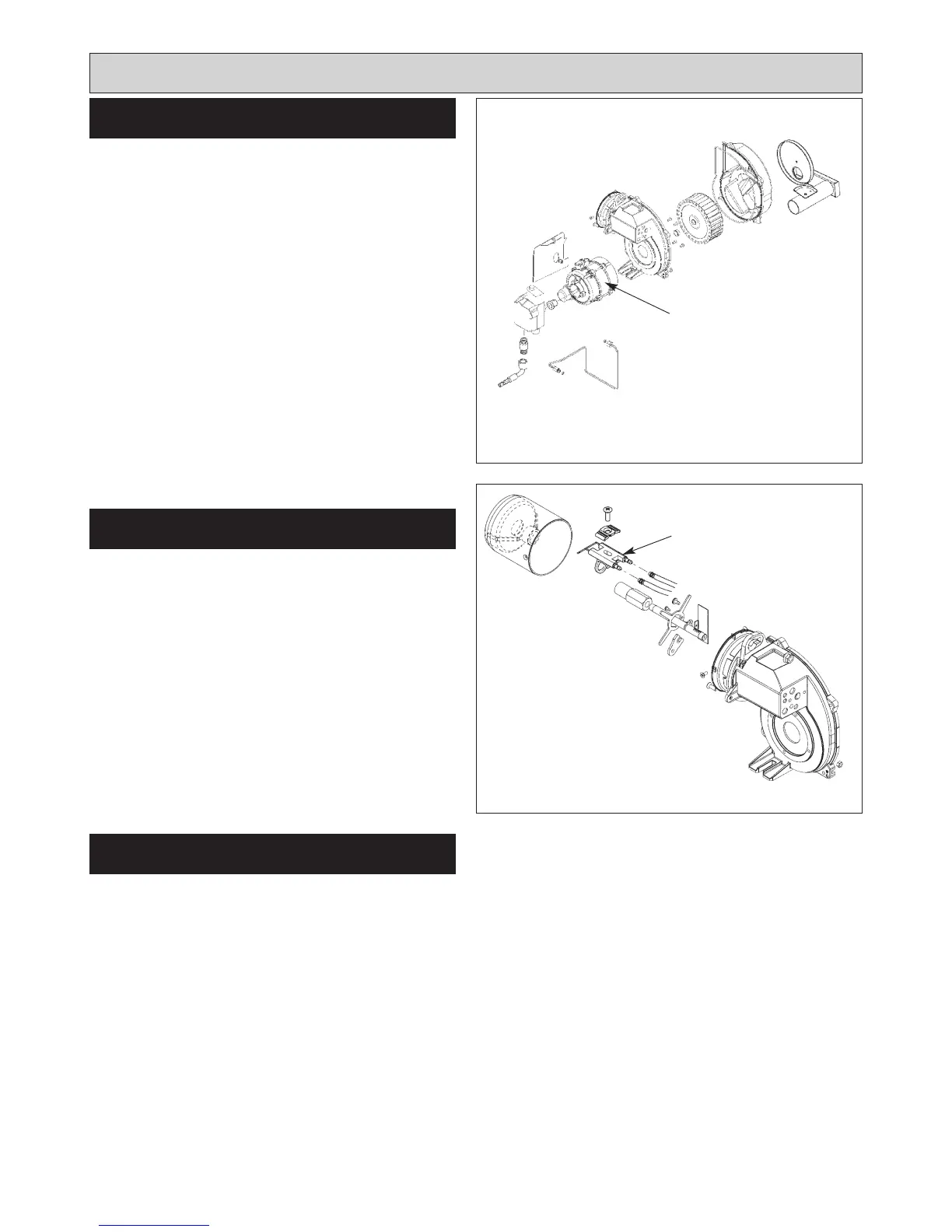
Follow instructions in BURNER ACCESS, Steps 1 to 3
and BURNER NOZZLE REMOVAL.
SEE FIG. 26
1. Release two countersunk head screws and remove
blast tube.
2. Remove two screws and slide out nozzle support
cradle c/w ignitor assembly from burner head.
3. Disconnect ignition leads.
4. Remove ignitor assembly by removing countersunk
screw and clamp.
5. Fit new ignition electrode assembly, re-assemble in
reverse order.
6. Check electrode gap and reset if necessary.
Follow instructions in sections BURNER ACCESS, Steps
1 to 3, and BURNER REMOVAL.
1. Remove both HT leads from ignitor.
2. Remove mains plug from ignitor.
3. Remove 2 ignitor securing screws.
4. Remove ignitor.
5. Fit new ignitor, re-assemble in reverse order.
17
FAN MOTOR
Fig. 25 DESN 515970
IGNITION ELECTRODES
Replacement of parts (Burner)
Fig. 26
IGNITOR
DESN 515971
FAN MOTOR
IGNITOR