EasyManuals Logo

Raycus RFL-C100 User Manual

Raycus RFL-C100
49 pages
To Next Page IconTo Next Page
To Previous Page IconTo Previous Page
Page #32 background imageLoading...
Page #32 background image
Wuhan Raycus Fiber Laser Technologies Co., Ltd.
User Guide of RFL-C100~RFL-C2000S
28
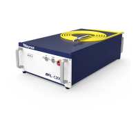
Figure 15 MOD Cable-The Cable for Modulation Signal
The modulation signal cable core is positive (24V) and the external metal
mesh is negative (GND). Before the modulated signal is connected to the
laser, please check the level.
Table 9 MOD definition
Name
OUT/IN
Function
Level
Example
min
max
MOD
Input
External signal
24V
24V
15V
28V
0V
0V
3V
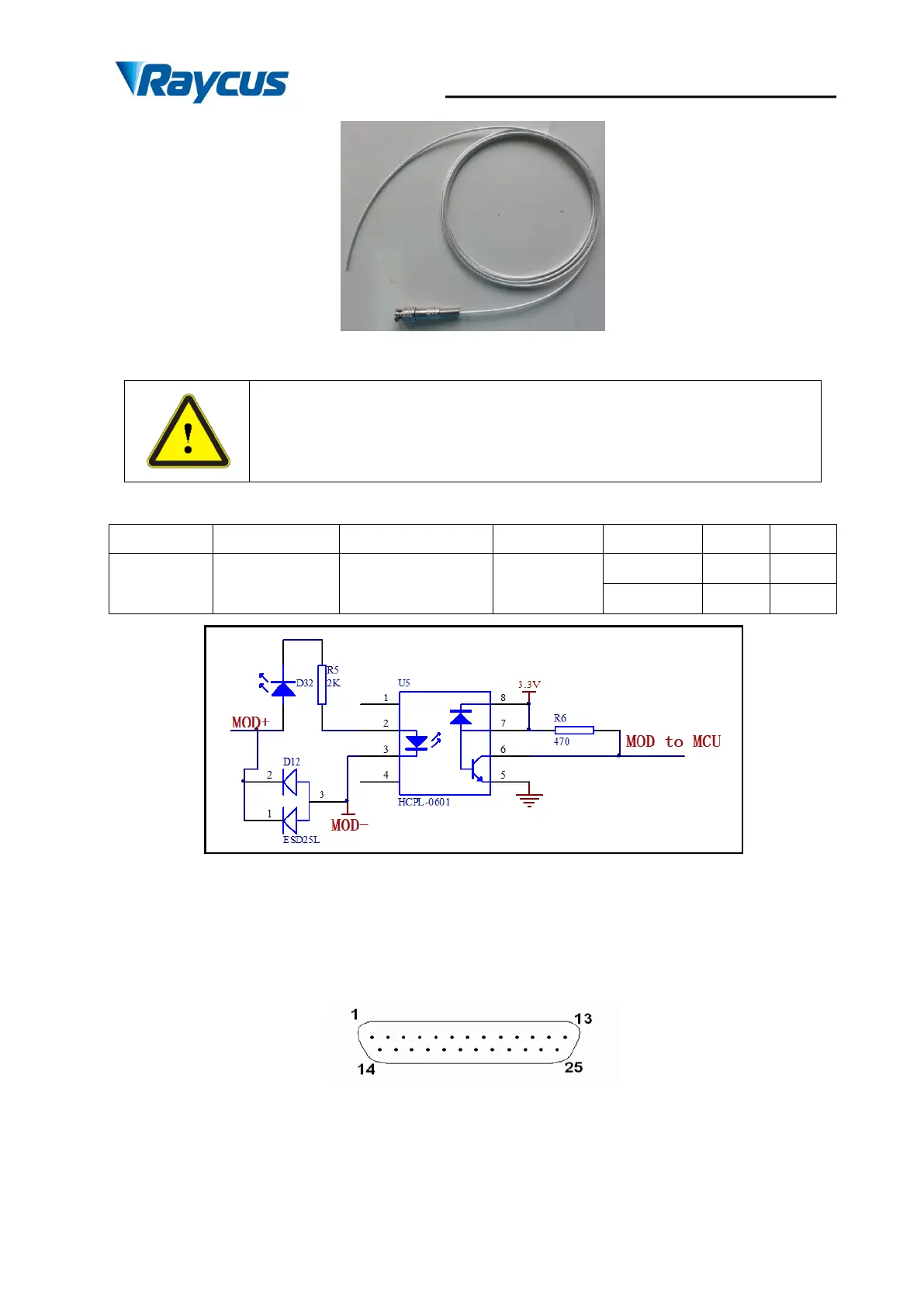
Figure 16 The internal circuit of the modulation signal
4.4.3 Control Interface
The pin number ofCTRL-INTERFACEis shown in Figure 17:
Figure 17 Pin Number of control Interface
The definitions of the control interface are as follows:
Table 10 Control Interface Definitions

Questions and Answers:

Question and Answer IconNeed help?

Do you have a question about the Raycus RFL-C100 and is the answer not in the manual?

Raycus RFL-C100 Specifications

General IconGeneral
BrandRaycus
ModelRFL-C100
CategoryMeasuring Instruments
LanguageEnglish

Related product manuals