Wuhan Raycus Fiber Laser Technologies Co., Ltd.
User Guide of RFL-C100~RFL-C2000S
25
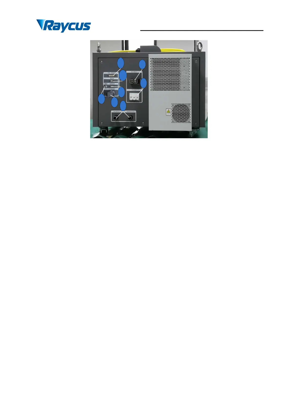
Figure 12 Rear Panel View of RFL-C1500S/C2000S
1. AC INPUT: The socket for supply source input that can only be mated with the plug on
the power cord we provided.
2. POWER: Air switch to control the switching of AC.
3. MOD: Modulation input, a signal for switching the laser on and off in remote control
modes. The control signal should be able to apply current over 20mA, and the voltage should be
24V.
4. CTRL-INTERFACE: Control interface, this interface is a male DB25 connector and
it’s multi-functional. The end users can set the control mode and input analog control signal with
the interface, as well as get the fault signal from it.
5. RS-232: RS-232 serial port, Provide remote control and alarm information storage for
the laser. Raycus provides a matching RS-232 serial communication cable.
6. SERVICE: Provide external functions of the customer. For details, please refer to 4.4
Interface and Definition.
7. WATER: Pipe connectors, the inlet and outlet for cooling water to flow in and return.
(See Table 6 for the laser model and corresponding water pipe size for cooling system
requirements ).