7
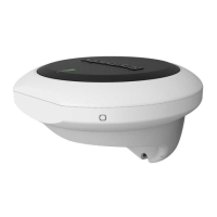
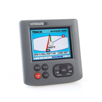
.Autopilotcontroller
8.ACU
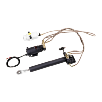
9.Driveunit(example)
10.Rudderanglereferencesensor/transducer(M81105)
Powerconnection—ACU-100,ACU-150
PowertotheACU-100andACU-150mustbefromanappropriatelyfusedandratedsupply.
1.A CU-100,ACU-150powerconnectionpanel
2.Vesselpowerdistributionpanel
Powerconnectioncolors
ColorDescription
AR ed
PowerinPositive(+)12Vdc
BBlack
P owerinNegative(–)0Vdc
Warning:Positivegroundsystems
Donotconnectthisunittoasystemwhichhaspositivegrounding.
Fusesandcircuitprotection
Thereare3levelsofpowerprotectionintheautopilotsystem.Thedrive(motor)andassociated
cablesareinitiallyprotectedbythecurrentsensingandstallconditiondetectionwithintheA CU
hardwareandsoftware.AsecondlevelofprotectionisprovidedtothesepartsandtheACU
componentsbytheACU'sinternalpowerfuse.Protectionfortheentireautopilotsystemandits
wiringbacktothemainpowerdistributionpanelisprovidedbyyourvessel’scircuitbreaker/fuse.
Powersupplycircuitprotection
ProtectthepowersupplyfortheEvolutionsystematthedistributionboardwithafuseorcircuit
breakerthatissuitablefortheACU.Forguidance,refertomainpowerfuseratingstatedontheACU
connectorpanel.Ifindoubt,consultyourlocaldealer.
70

 Loading...