Chapter 5: Installation 5-11
5.6 Cable Running
Introduction
The minimum requirements are a power cable and a connection from the
associated GPS Antenna. Additional cables will be required if you are
connecting to other equipment.
Consider the following points before installing the system cables:
• All cables should be adequately cleated and protected from physical
damage and exposure to heat. Avoid running cables through bilges or
doorways, or close to moving or hot objects.
• Where a cable passes through an exposed bulkhead or deckhead, a
watertight gland or swan neck tube should be provided.
• If an extension is required for the antenna cable it should be limited to a
single extension and kept as short as possible to minimise any signal
loss.
• The antenna cable should not be run close to any VHF antenna feeds.
Cross coupling between the cables may result in interference of the
GPS receiver and possible reduction in performance.
Connectors
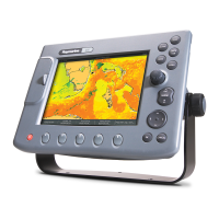
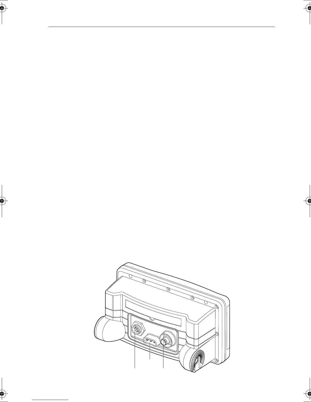
Run the following cables from the connectors provided at the rear of the
plotter as shown in Figure 5-6:
•
ANTENNA, for connection to the associated GPS antenna.
•
PWR/NMEA, for DC power and NMEA inputs/outputs.
•
SeaTalk, using the dedicated SeaTalk connector.
Figure 5-6: Raynav 300 Rear Connector Panel
PWR/NMEA
SeaTalk
Antenna
D5847-1
81171_4.BOOK Page 11 Thursday, November 29, 2001 11:34 AM