Item Cable color Signal name
1 Black Piezoceramic –
2 Blue Piezoceramic +
3
Screen 0 V (shield)
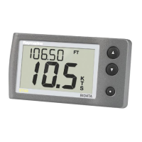
i40 Speed connection
Item Cable color Signal name
1 Brown Temperature 0 V
2 White
Temperature (signal)
3
Screen Speed 0 V (shield)
4
Green Speed (signal)
5
Red
Speed V+
i40 Wind connection
Item Cable color Signal name
1 Red Rotor +
2 Blue Rotor –
Making transducer connections
Although the transducer cable is tted with spade connectors for
direct connection to the rear of the unit, it may be necessary to
remove these to facilitate installation, e.g. if the cable has to be
routed through narrow apertures. 1/8th spade terminals will be
required (not supplied), to replace those removed. When tting the
new spade connectors, prepare the cables as detailed below:
1. Prepare the cable as shown in 1 above.
2. Fold back the wire strands and insert into the new spade
connector as shown in 2 above.
3. Ensure the wire strands do not extend beyond the rear of the
spade connector insulation.
4. Crimp the connector to the wire.
Cables and connections 19

 Loading...