** Subtract 10 ft per elbow. Max. 4 elbows.
t
Adapters supplied by others.
Category III Horizontal Vent & Horizontal Direct Vent
Model
No.
Certified
Vent
Material
Vent
Size
(in.)
Maximum
Horizontal
Vent Length
(ft)**
Combustion Air
Intake Pipe
Material
Air Intake
Max. Length** (ft)
4” Ø
259
Category III
6 80
Galvanized Steel,
PVC,
ABS,
CPVC
80
409
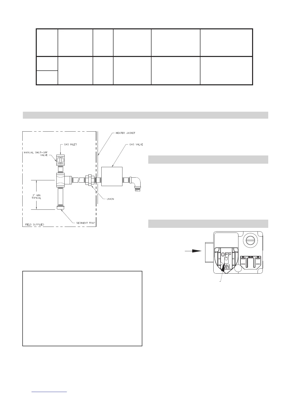
GAS SUPPLY CONNECTIONS
!4F C<C<A: @HFG ;4I8 4 F87<@8AG GE4C 4;847 B9 G;8
;84G8E:4F6BAGEB?F4A74@4AH4?F;HGB99I4?I8?B64G
87BHGF<78G;8;84G8E=46>8G??:4FC<C<A:F;BH?758
G8FG8749G8E<AFG4??4G<BA<A466BE74A68J<G;?B64?6B78F
CAUTION: The heater and its manual shut-off valve
must be disconnected from the gas supply during any
pressure testing of that system at test pressures in
excess of 1/2 psi (3.45 kPa). Dissipate test pressure
in the gas supply line before reconnecting the heater
and its manual shut off valve to gas supply line. FAIL-
URE TO FOLLOW THIS PROCEDURE MAY DAM-
AGE THE GAS VALVE. OVER PRESSURIZED GAS
VALVES ARE NOT COVERED BY WARRANTY. The
heater and its gas connections shall be leak tested
before placing the appliance in operation. Use soapy
water for leak test. DO NOT use open flame.
NOTE: Do not use Teflon tape on gas line pipe
thread. A pipe compound rated for use with natural
and propane gases is recommended. Apply sparingly
only on male pipe ends, leaving the two end threads
bare.
@<A<@H@B9<A04A74@4K<@H@B9<A0
HCFGE84@CE8FFHE8HA78E?B474A7AB?B476BA7<G<BAF
@HFG58CEBI<7879BEA4GHE4?:4F@<A<@H@B9<A
0 4A7 4 @4K<@H@ B9 <A 0 4E8 E8DH<E87 9BE
CEBC4A8:4FHA78E?B474A7AB?B476BA7<G<BAF
-;8 946GBEL @4A<9B?7 CE8FFHE8 F8GG<A:F F;BH?7
58VRPV09BE8<G;8EA4GHE4?BECEBC4A8:4F
SUPPLY PRESSURES
GAS PRESSURE ADJUSTMENT LOCATIONS
GAS INLET
GAS CONTROL
SWITCH SHOWN IN
“OFF” POSITION