HIGH LIMIT REMOVAL
,;HGB99@4<A8?86GE<64?CBJ8EFJ<G6;GB;84G8E
+8@BI89EBAG7BBE
+8@BI878986G<I8;<:;?<@<G4A7E8C?468J<G;4
A8J;<:;?<@<G
+8C?468<AFC86G<BAC4A8?
NOTE: An erratic high limit is often characteristic of an
internal heat exchanger problem, e.g. scale build-up,
defective bypass. Refer to Troubleshooting section
(starting on page 43).
-;8;84G8E<F8DH<CC87J<G;GJB4HGB@4G<6;<:;?<@<GF
BG;4E8?B64G87<AG;8<A?8GBHG?8G;8478EBG;4E8F8G
GBBC8A4GN
TIME CLOCK/FIREMAN’S SWITCH
-B BC8E4G8 G;8 ;84G8E J<G; 4 G<@8 6?B6> 6BAA86G G;8
G<@8EGBG;89<E8@4AXFFJ<G6;6BAA86G<BA<AG;8;84G8EXF
J<E<A: -;8 G<@8 6?B6> F;BH?7 58 B9 G;8 7H4? FJ<G6;
GLC8 4A7 F8G GB F;HG B99 G;8 64?? 9BE ;84G GB G;8 CBB?
;84G8EGB@<AHG8FCE<BEGBF;HGG<A:7BJAG;8CBB?
CH@C-;89<E8@4AXFFJ<G6;6BAA86G<BA<F?B64G87BA
G;8C<A;8478E6BAA86G87GBG;87<:<G4?6BAGEB?5B4E7
,C?<68<AGBG;8E87J<E8=H@C8EG4::87U0;8E8A868F
F4EL477U <E8@4AXFVFJ<G6;6<E6H<G;8E8VGB6BAA86GG;8
G<@8 6?B6> The fireman’s switch connection must
be a dry contact and must not supply power to the
heater. Powering the fireman’s switch connection
externally may damage the heater, and is not
cov-
ered by warranty.
B ABG 8K6887 9G B9 GBG4? J<E<A: HF<A: 0!
FGE4A787 6BCC8E J<E8 E4G87 9BE Q Q @<A<
@H@
NOTE: When using a time clock, the heater will dis-
play “Clock/ Fireman Sw” when the fireman’s switch
is open, indicating that the time clock has shut off the
call for heat.
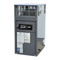
HIGH LIMITS
This standard, dual-purpose control, mounted and
wired in series with the main gas valve, shuts off
heater in case of pump failure or low water flow.
Flow Switch
FLOW SWITCH
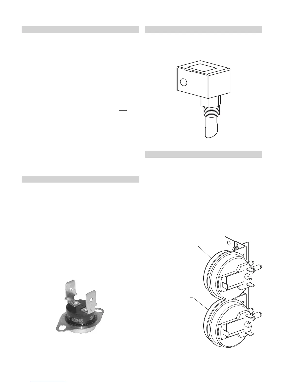
AIR PRESSURE & BLOCKED VENT SWITCHES
This heater is equipped with an air pressure switch to
prove the operation of the blower before allowing the
ignition control to begin a Call for Heat. It is also
equipped with a blocked vent pressure switch to pre-
vent the operation of the heater when too much of the
vent is blocked.
The two switches appear similar and are mounted next
to each other on the heater. They can be distin-
guished by their mounted positions and by the pres-
sure settings printed on the labels. See the diagram
below.
BLOCKED VENT SWITCH
0.4 ”W.C.
AIR PRESSURE SWITCH
2.5 ”W.C.
Air Pressure & Blocked Vent Switches