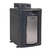
NOTE: To avoid water damage or scalding due to
valve operation, drain pipe must be connected to valve
outlet and run to a safe place of discharge. Drain pipe
must be the same size as the valve discharge connec-
tion throughout its entire length and must pitch down-
ward from the valve. No shut-off valve shall be
installed between the relief valve and the drain line.
Valve lever should be tripped at least once a year to
ensure that waterways are clear.
PRESSURE RELIEF VALVE INSTALLATION
-B6BA9BE@GB ?B64?5H<?7<A: 6B78F <G@4L 58 A868F
F4EL GB <AFG4?? 4 CE8FFHE8 E8?<89 I4?I8 ;4I<A: 4
64C46<GL8DH4?GBG;8-."BHGCHGB9G;8@B78?-;8
@4K<@H@ 4668CG45?8 CE8FFHE8 E8?<89 I4?I8 F8GG<A: <F
CF<
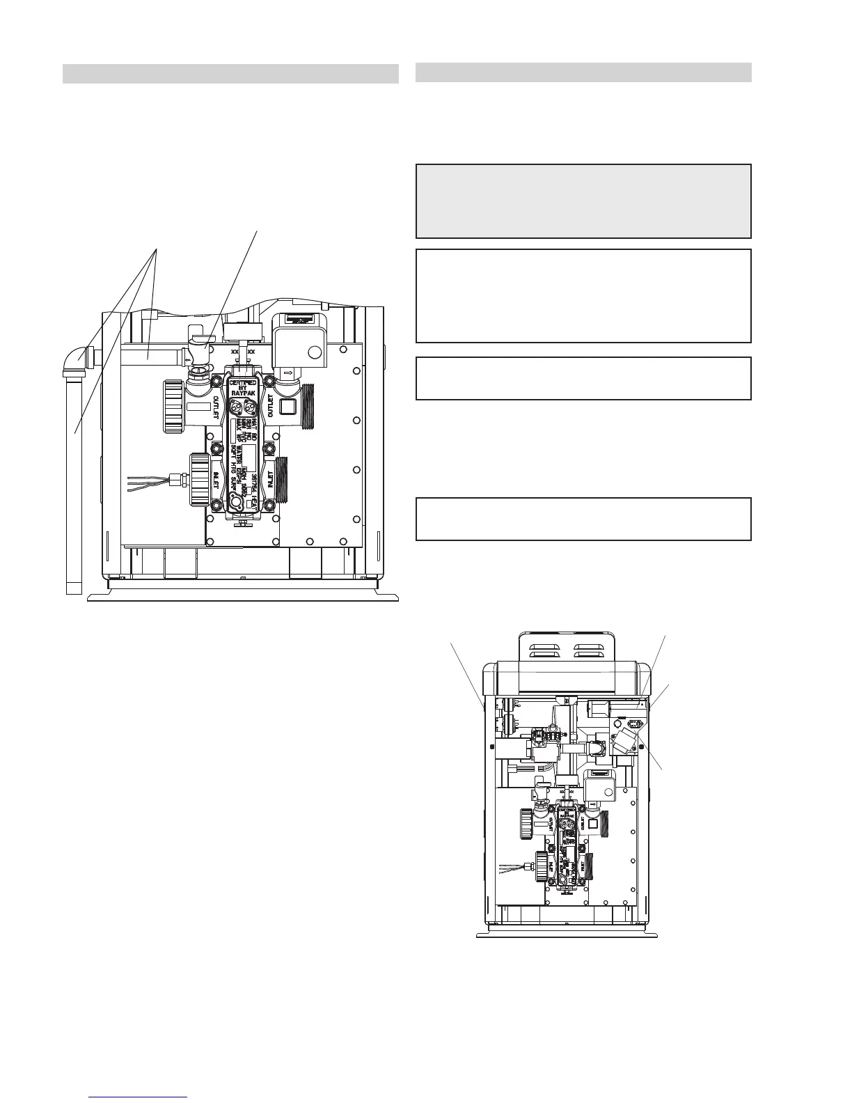
ELECTRICAL WIRING
NOTE: If it is necessary to replace any of the original
wiring, use 105°C wire or its equivalent, and/or 150°C
wire or its equivalent, like the original wiring.
WARNING: Heaters are factory-wired for
240)VAC power supply. DO NOT attempt to oper-
ate at or below 208)VAC.
CAUTION: Heater must be electrically grounded and
bonded. Bonding lug is provided loose with the
heater. Install bonding lug on lower right or left side
of jacket as necessary for bonding the heater.
Mounting hole is provided on the jacket.
-;8 ?86GEBA<6 #AG8E@<GG8AG #:A<G<BA 8I<68 4HGB@4G<
64??L?<:;GFG;8@4<A5HEA8EHCBA464??9BE;84G-;8
;84G8E<FFHCC?<87J<G;47H4?IB?G4:8GE4AF9BE@8E9BE
/BE/<ACHGCBJ8E;BB>HC
NOTE: 4<?HE8GB:EBHA7G;8;84G8E8?86GE<64??L
6BH?749986GG;8;84G8EXF8?86GEBA<6F
NOTE: ,88C4:89BE9HEG;8E<AFGEH6G<BAF<9HF<A:
4G<@86?B6>9<E8@4AXFFJ<G6;
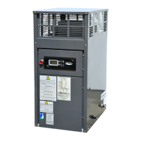
0<E<A:?B64G<BAF
CONTROL BOX
(FACTORY-MOUNTED
LOCATION)
FIELD WIRING BOX
RECOMMENDED
POWER SUPPLY
SIDE
OPTIONAL
POWER SUPPLY SIDE
(ROUTING TO WIRING
BOX REQUIRED)