33
R
eset Ratio 0.4 to 3.6 / Setpoint Target 120°F to 200°F
S
ingle Stage (On) / Two Stage (Off)
O
utdoor Reset (On) / Setpoint (Off)
Active 70°F (On) / Inactive (Off)
B
oiler Max
O
utlet Setting
B
oiler Maximum (dependent on DIP #5)
-
Default: On
o
If DIP #5 set to Hydronic (On): 210°F (Off) / 190°F(On)
o
If DIP #5 set to Direct DHW (Off): 180°F (Off) / 160°F(On)
Space Heating
or Direct
Domestic Hot
W
ater
Direct DHW (Off) / Hydronic (On) - Default: Hydronic (On)
Note: If DIP #5 is set to Direct DHW (Off), the operation is
b
ased on Setpoint regardless of DIP #2 setting.
Table O: Outdoor Air Reset Temperature Controller Settings
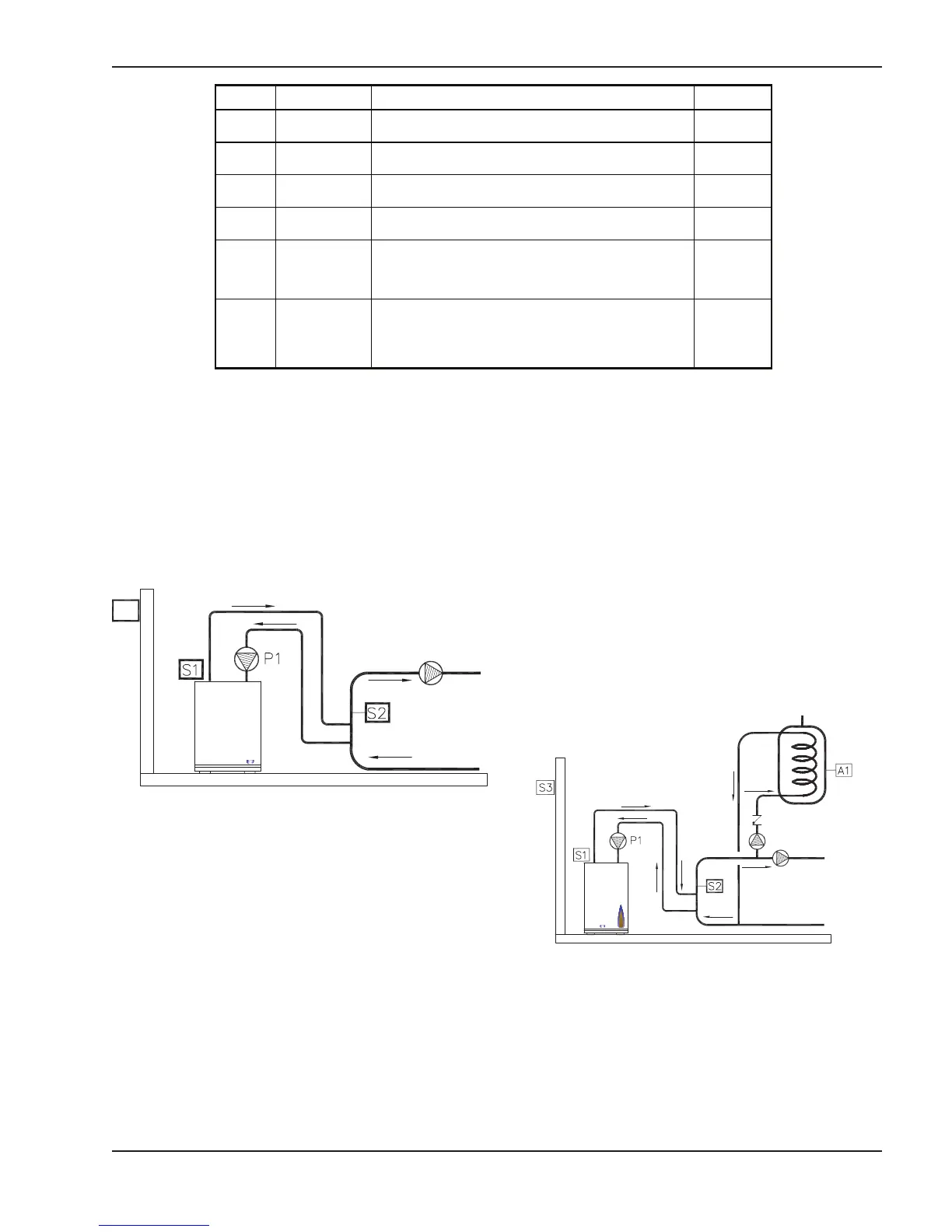
Hydronic with Outdoor Air Reset
For hydronic operation with outdoor air reset, the
System Supply Sensor (S2) is used as the operating
sensor. Boiler Outlet Sensor (S1) is used for boiler out-
let maximum limiting. Boiler Pump (P1) is controlled by
the boiler and is cycled off using a 5 minute fixed purge
delay after burner operation has ceased.
S1 = Boiler Outlet Sensor
S2 = System Supply Sensor
S3 = Outdoor Air Sensor
P1 = Boiler Pump
The DIP switch settings are as follows:
DIP 1 ON (ON/OFF) – OFF (2-STAGE)
DIP 2 ON (OUTDOOR RESET)
DIP 3 ON (WWSD 70°F)
DIP 4 ON (190°F BOIL MAX)
DIP 5 ON (HYDRONIC)
Fig. 25: Hydronic with Outdoor Air Reset
Hydronic, Outdoor Air Reset with
Indirect DHW
For hydronic operation with outdoor air reset and
Indirect DHW, the System Supply Sensor (S2) is used
as the operating sensor. Boiler Outlet Sensor (S1) is
used for boiler outlet maximum limiting. Contact clo-
sure from an aquastat located on an indirect DHW
tank will cause the controller to operate to a boost tem-
perature to satisfy the indirect call for heat. Once the
aquastat opens the controller will return to normal
operation. The indirect pump is operated by an exter-
nal relay (by others). The Boiler Pump (P1) is
controlled by the boiler and is cycled off using a 5
minute fixed purge delay after burner operation has
ceased.
The DIP switch settings are as follows:
DIP 1 ON (ON/OFF) – OFF (2-STAGE)
DIP 2 ON (OUTDOOR RESET)
DIP 3 ON (WWSD 70°F)
DIP 4 ON (190°F BOIL MAX)
DIP 5 ON (HYDRONIC)
Fig. 26: Hydronic with Outdoor Air Reset
and Indirect DHW