43
5. Turn power off.
6. Reinstall rubber plug on tee.
Main Burner Adjustment
1. Turn off unit.
2. Open manual firing valve.
3. Turn on the unit, wait 15 seconds, and the igniter
should glow. There’s a sight glass to check igniter
at both ends of the heater. Gas valve should be
open after 45 seconds.
4. If burner does not light on first trial. It will retry, up
to 3 times.
5. Main burner ignition – check manifold gas pres-
sure at gas valve manifold pressure tap. (See
Table P).
6. If the pressure reading differs by more than the tol-
erance given, adjust the gas valve accordingly.
See gas valve adjustment section below for
instructions.
Gas Valve Adjustment
Honeywell Gas Valve
1. While the heater is running, remove plastic cap
located behind ON/OFF knob.
2. Locate the HI or LO screw to adjust.
3. Using a small flat screwdriver, turn clockwise to
increase and counterclockwise to decrease mani-
fold pressure. See nominal gas valve manifold
settings in Table P above.
4. Replace plastic cap when pressure is set.
White Rodgers Gas Valve
1. While the heater is running, locate the HI or LO
cap located adjacent to ON/OFF switch.
2. Remove the appropriate cap.
3. Using a flat screwdriver, turn clockwise to increase
and counterclockwise to decrease manifold pres-
sure. See nominal gas valve manifold settings
above.
4. Replace cap(s) when pressure is set.
Invensys (Model HD401 Natural
Only)
1. Turn heater off.
2. Locate and remove the Torx tamper resistant
screw. (Shown in Fig. 35)
3. Carefully remove 2-stage solenoid.
4. Skip to Step 9 for LO-fire adjustment only.
5. Locate and remove Lo-fire adjustment cap.
6. Carefully remove the spring & weight.
7. Using an allen wrench, turn clockwise to increase
and counterclockwise to decrease the HI-fire man-
ifold pressure. Heater will not run while adjusting
HI-fire pressure.
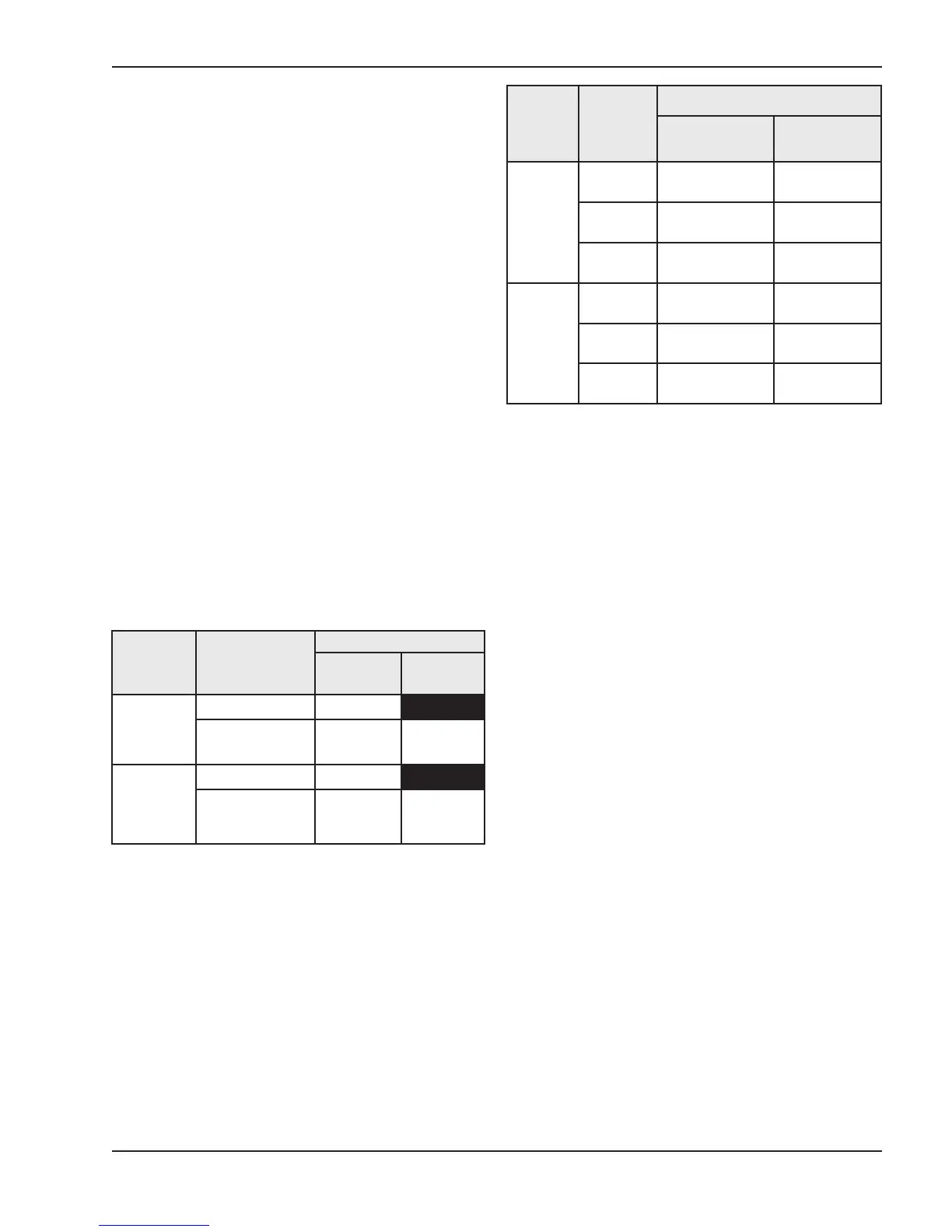
Table P: Gas Valve Pressures
Table Q: Expected Settings
Firing
Stage
Gas Valve
Gas Type
Natural
LP/
Propane
Hi-Fire
+/- 0.2"WC
Invensys 3.4" WC
Honeywell or
White-Rodgers
3.1" WC 9.6" WC
Lo-Fire
+/- 0.1"WC
Invensys 1.1" WC
Honeywell or
White-Rodgers
1.2" WC 3.6" WC
F
iring
Stage
E
xpected
Settings
Gas Type
Natural
LP/
Propane
Lo-Fire
C
O2
8
.2 +/- 0.2%
9
.7 +/- 0.3%
CO < 50ppm < 50 ppm
Air
0.45” +/- 0.05”
WC
0.45” +/- 0.05”
WC
Hi-Fire
CO2 8.7 +/- 0.2% 10.1 +/- 0.4%
CO < 100ppm < 100ppm
Air
1.05” +/- 0.1”
WC
1.05” +/- 0.1”
WC