AUTO H SETTING - MIN TRIM HEIGHT
This is the low limit for the array and is defined as the smallest allowable distance from the
lowest point of the array to the ground below
AUTO H SETTING - MAX SUSPENSION POINT
Set this to the maximum array height allowable (usually the highest part of the flying frame).
The maximum pick height is usually chosen to allow for the maximum flying point height
minus a sensible allowance for any shackles, stingers, bridles or flying hooks. 1m should be
allowed for a stinger between each grid flying lug and the relevant motor hook to ensure that
motor chain bags do not rest on the grid or top cabinet and upset its tilt angle.
MANUAL H SETTING
In manual installation mode it is possible to enter the height required for flying the system.
Number of cabinets can be set depending also on cabs availability.
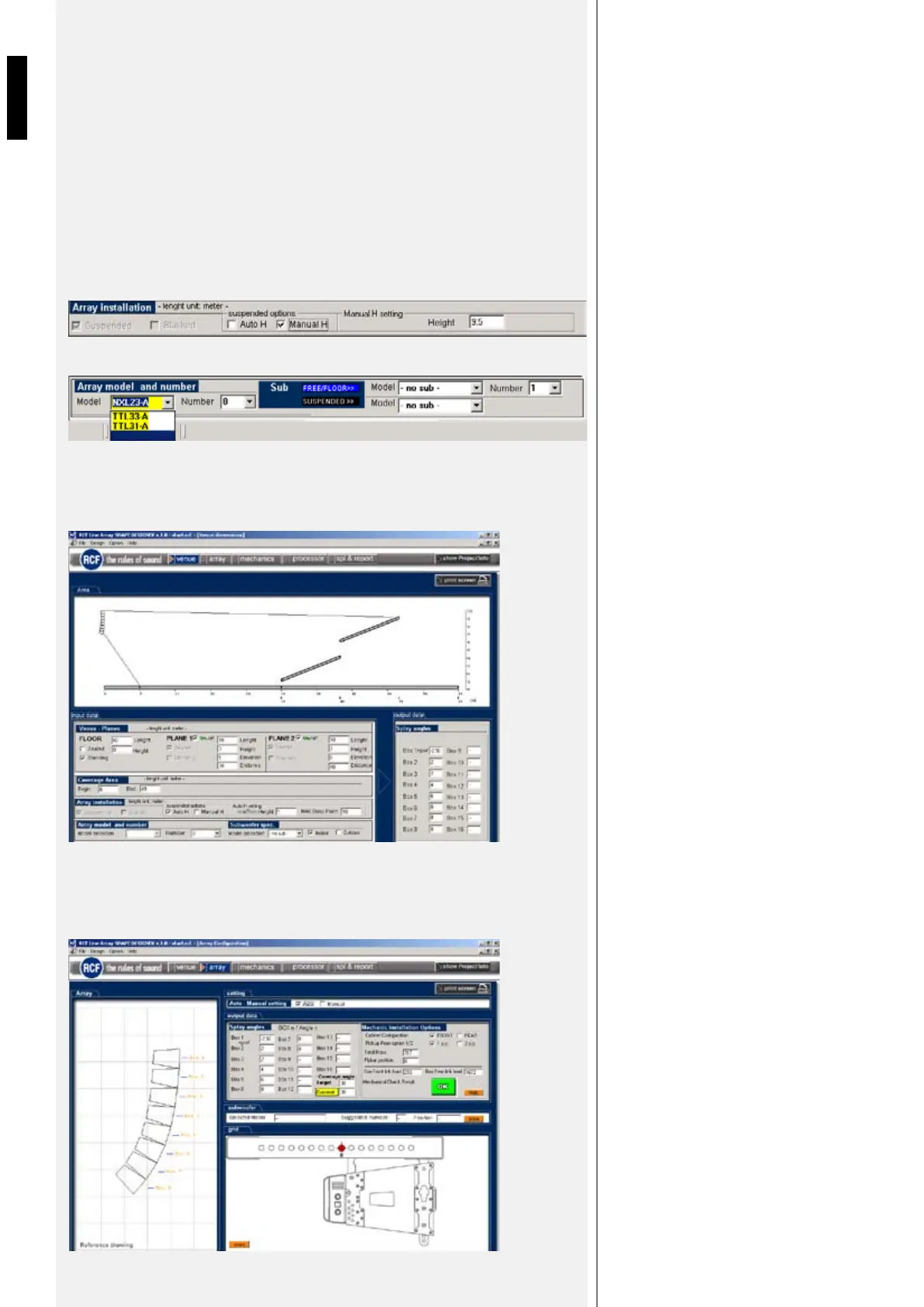
VENUE PAGE
- Graphical representations of the array and the venue
- Aiming splay angle between each pair of enclosures
- Height of the array and trim height to the bottom of the array from the floor
- Pick Point on the Fly-Bar to achieve the calculated array angle when suspended
- Weight of the array
- Mechanical check result
SUSPENDED MODE
NUMBER OF CABINETS AND
SUBWOOFERS
RCF SHAPE DESIGNER RESULTS
ARRAY PAGE
HDL20-A
 Loading...