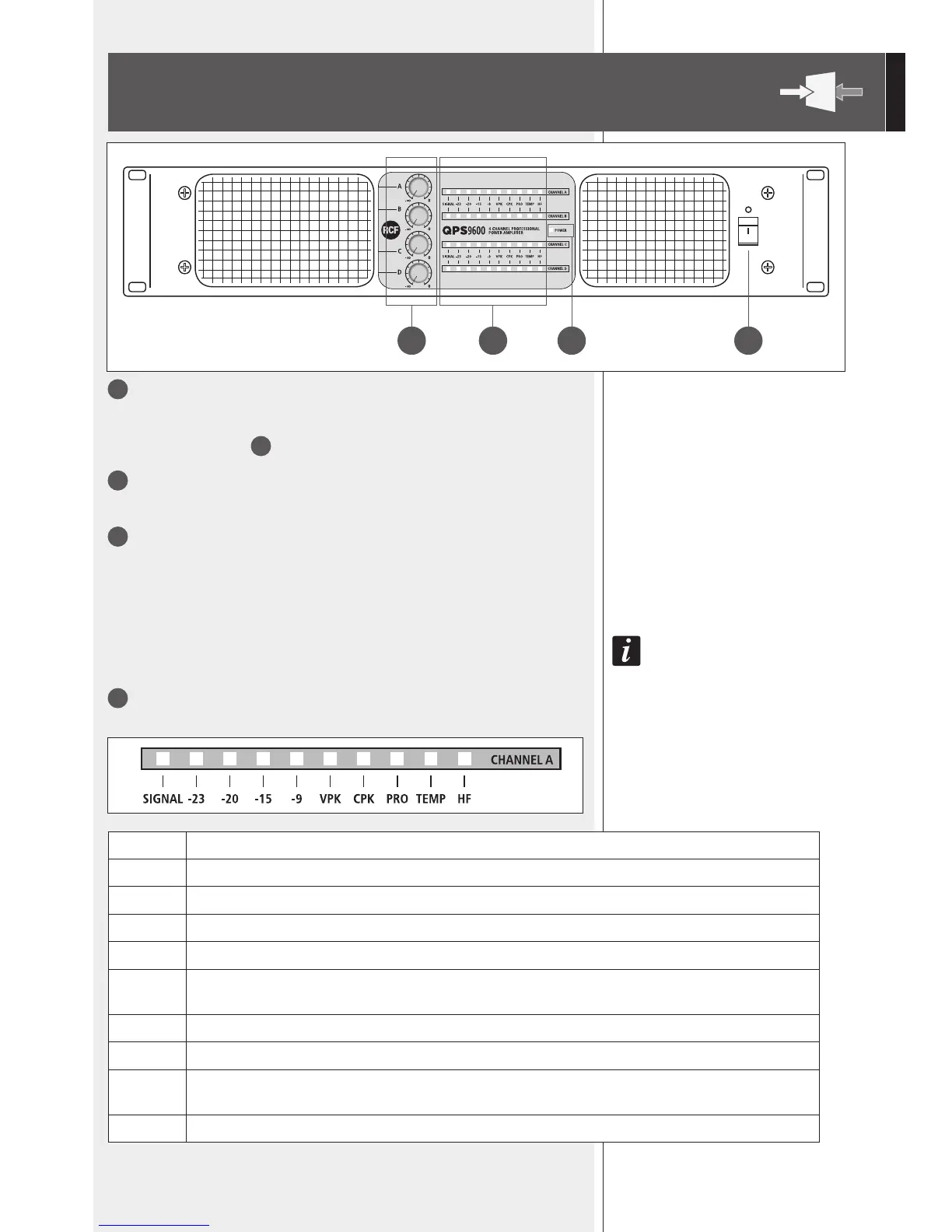
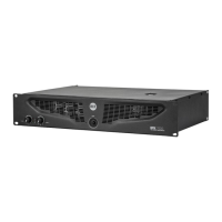
FRONT PANEL
1
POWER switch with LED
Push to turn on (I) / off (O) the amplier. Its LED is lit when the amplier is turned on.
Before switching the amplier on, check all cables and turn fully counterclockwise all the
four channel level controls
3
.
2
POWER LED
When lit, the amplier is switched on.
3
Controls (one per channel) to adjust the output level of the respective amplier
channels.
Turn clockwise to increase the output level (0 dB = max. level), turn counterclockwise to
decrease.
Set the control of an unused channel to – (fully counterclockwise).
If channels a and B are BrIdged, use the channel a control only. If channels c and d are BrIdged,
use the channel c control only.
4
LED bar per each channel
3 4 2 1
SIGNAL When lit, it indicates the signal presence at the respective input.
–23 When lit, it indicates a signal level of (at least) –23 dB at the respective input.
–20 When lit, it indicates a signal level of (at least) –20 dB at the respective input.
–15 When lit, it indicates a signal level of (at least) –15 dB at the respective input.
–9 When lit, it indicates a signal level of (at least) –9 dB at the respective input.
VPK
It blinks when the signal level reaches the clipping point, causing the limiter intervention on the respective channel.
If it is steady lit, the input signal level is excessive and should be reduced.
CPK If steady lit orange: load having a too low impedance / short circuit detected (the respective output is muted).
PRO When lit, it indicates the internal protection intervention and the respective channel is muted.
TEMP
When lit, it indicates the internal protection intervention due to thermal drift.
The respective channel is muted.
HF If steady lit yellow: high frequency protection insertion. The respective output is muted.