7
EN
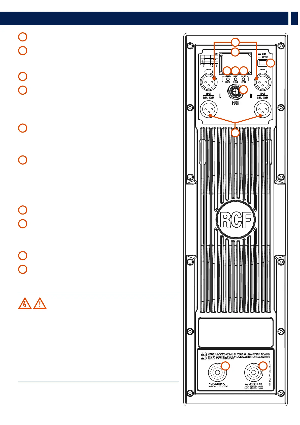
3. REAR PANEL FEATURES AND CONTROLS
1
FEMALE XLR INPUTS L and R The system accepts XLR input connectors�
2
MALE XLR SIGNAL OUTPUTS The output XLR connectors provide a loop through for
speakers daisy chaining� The balanced connectors are connected in parallel, and can be
used to send the audio signal to other amplified speakers or supplementary amplifiers�
3
SYSTEM SET UP ENCODER
4
GAIN REDUCTION / POWER LED
- POWER LED This green LED lights up when the speaker is connected to the main
power supply�
- GAIN REDUCTION LED Pushing the encoder once, the gain reduction indicator
lights up green� Then, rotating the encoder, the gain level can be set to the right level�
5
DELAY / SIGNAL LED
- DELAY LED Pushing the encoder twice, the delay indicator lights up green� Then,
rotate the encoder to delay the speaker� The delay is expressed in meters�
- SIGNAL LED This indicator lights up green if there is an audio signal on the main�
6
PRESET / LIMITER LED
- PRESET LED Pushing the encoder three times, the preset indicator lights up green�
Then rotate the encoder to load the right preset to the speaker�
- LIMITER LED The amplifier has a built-in limiter circuit to prevent any amplifier
clipping or transducers overdrive� When the soft clipping circuit is active, the LED blinks
RED� It is okay if the limiter LED blinks occasionally� If the LED lights continuously, turn
down the signal level�
7
SYSTEM SET UP DISPLAY It displays the system setting values�
8
LINK/XOVER SELECTOR When the selector is set to LINK position, the input signal
is sent directly to the output signal� When the selector is set in XOVER position, a
crossovered signal will be applied to the outputs to optimize the signal sent to any
speaker connected�
9
AC POWER INPUT Powercon locking 3-pole AC mains�
10
AC OUTPUT LINK Sends the AC power to another speaker�
Power link: 100-120V~16 A MAX 1600W l 200-240V~16 A MAX 3500W�
WARNING! CAUTION! Loudspeaker connections should be only
made by qualified and experienced personnel having the technical know-
how or enough specific instructions (to ensure that connections are made
correctly) in order to prevent any electrical danger�
To prevent any risk of electric shock, do not connect loudspeakers when the
amplifier is switched on�
Before turning the system on, check all connections and make sure there are
no accidental short circuits�
The entire sound system shall be designed and installed in compliance with
the current local laws and regulations regarding electrical systems�
3
8
2
4 65
7
1
9 10