WARNING
TO BE USED ONLY FOR
STACKING APPLICATIONS UP TO
4 TTL33 MODULES NEVER USE
FOR SUSPENDING SPEAKERS
AVERTISSEMENT
EMPLOYER SEULEMENT POUR
EMPILER JUSQUE A 4 MODULES
TTL33 NE JAMAIS EMPLOYER
POUR SUSPENDRE DES
HAUT-PARLEURS
CONFIGURATION
HOLE ON THE FRAME
7
5
3
0
7
5
-6
-8
-6
-8
1 2 3
31
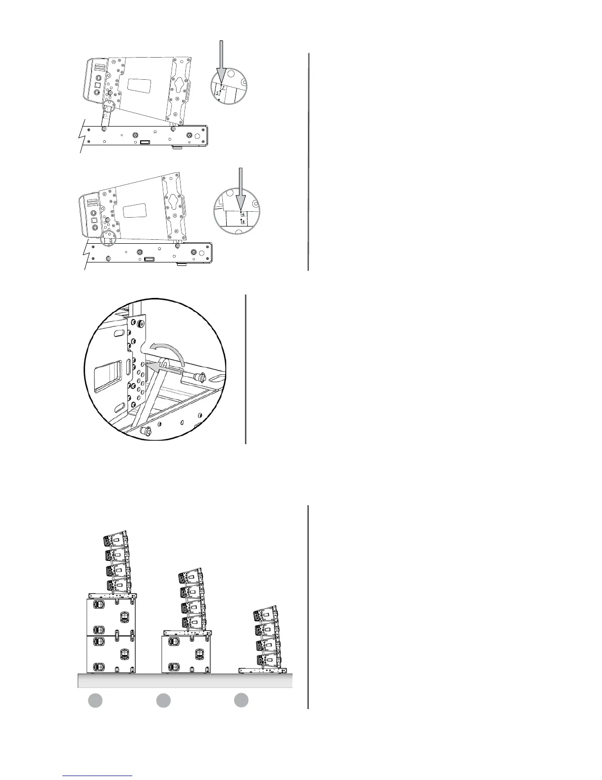
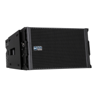
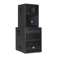
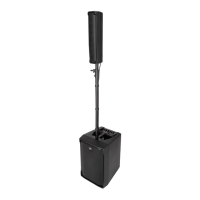
The bottom box in a stacked array can be tilted with
2 degrees steps to obtain proper coverage patterns
(from +11° to –8°) as shown in the figure.
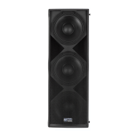
Reverse and connect the 2 rear STCK BAR TTL33A bracket to the first
enclosure using the hole for the proper angle and quick lock pins
Add TTL33A cabinets one by one as indicated for flown configurations. Up to four TTL33A enclosures can be stacked and
interlinked using the standard TT+ rigging components and the FLY BAR TTL33A flying frame as ground support.
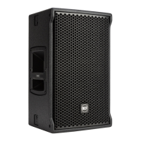
Ground stacking summary: possible configurations
The configuration No. 1 requires:
No. 1 Stack bar accessory STCK BAR TTL33A p/n 13360057 of
which all bars will be used, and additional Nos 16 pins (Nos 4
AC-QL PIN4X p/n 13360060).
The configuration No. 2 requires:
No. 1 Stack bar accessory STCK BAR TTL33A p/n 13360057 of
which only 2 bars type A) and 2 bars type B) will be used, and
additional Nos 8 pins (Nos 2 AC-QL PIN4X p/n 13360060).
The configuration No. 3 requires:
No. 1 Stack bar accessory STCK BAR TTL33A p/n 13360057, of which
only 2 bars type B) will be used, and no additional pins are required.