18
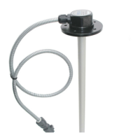
Pic. 8.8 Scheme of connection of interface and connecting cables
Additional instructions of connecting of the sensor to different control units, concentrators and
equipment of GPS - monitoring are in the appendixes of this Manual:
- for "Dalcon" concentrator – Appendix 4
- for "АвтоГРАФ –GSM" system – Appendix 5
- for "Teletrack" system – Appendix 6
- for "IntelliTrac" system – Appendix 7
- for "Teltonika" system – Appendix 8
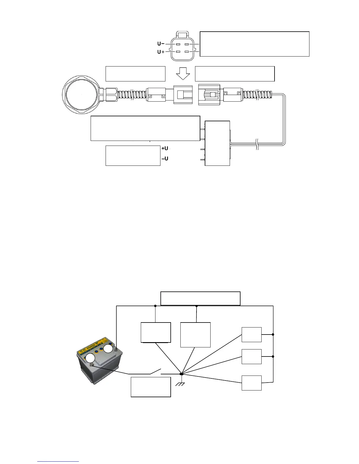
Common earth conductors of the sensor (black wire) and of a control unit must be connected to
a single point on the chassis of a vehicle, to which "mass" or "earth" of the other electrical
appliances of a vehicle are connected (Pic. 8.9).
ДУТ
БУ
-
Выключатель
массы
1
2
...
n
Электроприборы ТС
+
Pic. 8.9 CORRECT connection of common wire
Interface cable Connecting cable
Yellow
Green
Red
Blac
k
 Loading...