EPSILON ES2,ES4
17
Install the plug on the cap, shown in Picture 8.5, on the right, and push until it clicks.
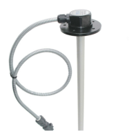
Preparation of the sensor for installation is complete. If the sensor is supplied with a probe of
unified or special length, the sensor assembly and preparation for installation is performed in
factory conditions.
8.3 Sensor’s installation on fuel tank
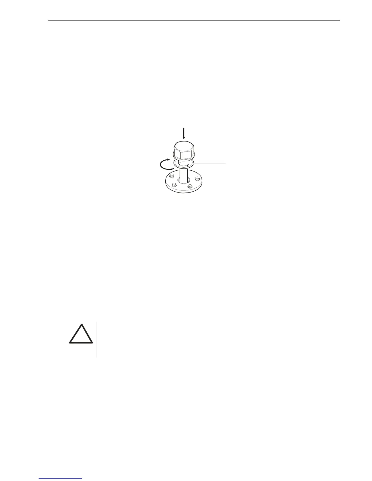
The sensor is screwed into the threaded hole of the flange as it shown in Pic. 8.7. Tightness of
connection is ensured by a sealing ring located in the front groove of the measuring head.
Before installing the sensor it is recommended to put a thin layer of grease or engine oil to the
ring.
Pic. 8.7 Installation of assembled sensor on fuel tank
8.4 Connection of sensor to control units
To connect the sensor to different control units, concentrators and equipment of GPS -
monitoring it is recommended to use the original sensor’s cable system, which consists of an
interface cable ES.120 (0.45 m) and a connecting cable ES.300 (7,5 m).
The interface cable is connected to the measuring head of the sensor with help of permanent
connection and ends with slot M (6188-0442) (plug, set).
Connecting cable is supplied with the sensor. It begins with slot F (6189-0656) (socket, set) and
ends with four pressed wires, which should be connected to the appropriate type of the input
connector of a device.
Scheme of connection of interface and connecting cables and the wires description as well are
shown in Pic. 8.8.
!
WARNING! Do not twist the cable entry or otherwise violate the integrity
of the measuring head from the input of interface cable.
The connecting cable is stretched from the sensor which installed on the fuel tank, to the control
unit, that is usually located in the driver’s cab through the technologic holes, provided by the
construction of a vehicle. The cable is fixed with ties on immovable parts of the construction
every 50-60 cm.
Rubber sealing ring