P a g e | 5 Bee8 User’s Manual Reach/BTX
Section 2 Connection Example
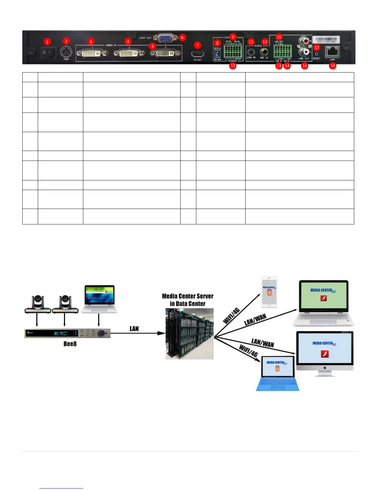
Figure 1. Conceptual Flow
RS422/RS485 External control
connection (phoenix connector)
120-240 VAC to DC Brick 12V/10A
power input
2 channel 3.5mm TRS line in
Unbalanced microphone input (Hi-Z)
2 channel line in, unbalanced (phoenix
connector) (Hi-Z)
Line in loop out (phoenix connector)
Analog VGA signal loop for DVI In 3
Balanced microphone input (phoenix
connector) (Low-Z)
RS232/RS485 switch for camera
PTZ control
Reset to factory default momentary
switch
RS232 or RS485 camera PTZ control
connection (phoenix connector)
Ethernet network connector