15
Fig.4.7
FENCE BAR
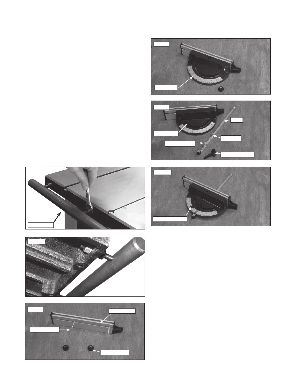
4.6 Fitting the fence bar
Attach the fence bar to the table as shown in Fig. 4.7, ensuring the
washers are placed next to the fixing nuts. Use the remaining 2 nuts and
washers to secure the fence bar from the underside of the table, Fig. 4.8.
Do not fully tighten yet as adjustment may be necessary.
4.7 Assembling the mitre fence
1. Unscrew the locking nuts from the mitre fence Fig.4.9.
2. Place the protractor with the flat edge running parallel to the
mitre fence.
3. Position it in such a way that the fence screws slot into the holes on the
protractor Fig.4.10.
4. Replace and re-tighten the locking nuts.
5. Position the slide underneath the protractor so that the threaded bar sits
in the angle slide and the pivot pin inserts into the pivot hole Fig.4.11
and Fig.4.12.
6. Tighten the ratchet handle onto the threaded bar Fig.4.12.
4. Machine Assembly - cont.
Fig.4.9
Mitre Fence
Fence Screws
Locking Nuts
Fig.4.10
Protractor
Fig.4.11
Slide
Angle Slide
Pivot Pin
Threaded Bar
Ratchet Handle
Fig.4.12
Ratchet Handle
Fig.4.8
 Loading...