12
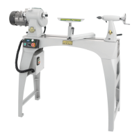
Fig 9.2
Tailstock
Attach
headstock
using these
holes
Plinth
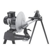
Using an 18 mm wrench (not supplied) attach the upright column to the
base using 2 M10 x 80 mm bolts, ensuring that there is an M10 washer
between each bolt and the upright column and another M10 washer
between each M10 nut and the base, Fig 9.1. Repeat this process to
assemble the second base onto the second upright column.
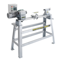
Using a 16 mm wrench (not supplied) attach the upright plinth to the
upright column using 2 M10 x 80 mm bolts to the desired height, ensuring
that the plate on top of the plinth which will hold the headstock end of the
lathe is oriented as shown in Fig 9.2. Also ensure that there is at least 1
hole space between the 2 bolts and that both bolts pass through the upright
column. Fig 9.3. Repeat this process to complete assembly of the second
leg.
Please note: The leg stand is adjustable in height to allow for
comfortable use of the lathe. As a general rule, the centre height
of the lathe should be at elbow height.
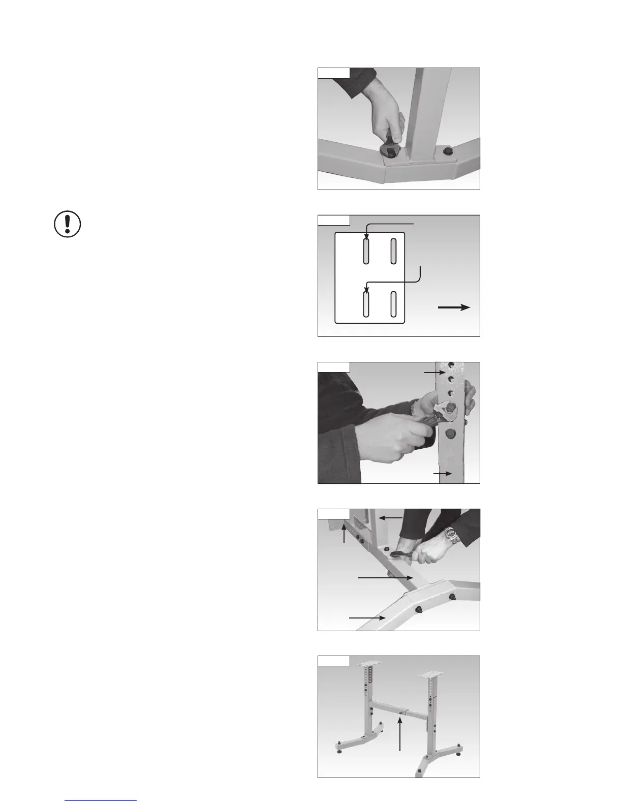
Using a 16 mm wrench (not supplied) attach the female cross brace to one
of the upright columns using two M10 x 80 mm bolts. Attach the male cross
brace to the remaining upright column in the same manner, Fig 9.4.
To complete assembly of the leg stand, insert the male cross brace into the
female cross brace, ensuring that the distance between the mounting holes
on the plinths is 725 mm. Using a 16 mm wrench (not supplied) hold in
place with 2 M10 x 25 mm hex head screws, Fig 9.5.
The remaining bolts, nuts and washers are used to attach the lathe to
the stand.
9. Assembly of the Optional DML305/A Leg Stand