14
10. Assembly of the Optional DML305/L Extension
Support and DML250 Bed Extension
Assembly of the DML305/L Extension Support
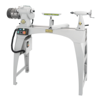
Attach the upright column to the base using 2 M10 x 80 mm bolts, ensuring
that there is an M10 washer between each bolt and the upright column and
another M10 washer between each M10 nut and the base, Fig 10.1.
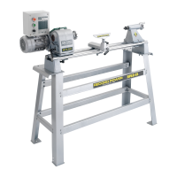
Attach the upright plinth to the upright column using 2 M10 x 80 mm bolts
to the desired height, making sure that the overhang of the plate on top
of the plinth is facing towards the inside of the legstand. Also ensure that
there is at least one hole space between the 2 bolts and that both bolts pass
through the upright column, Fig 10.2.
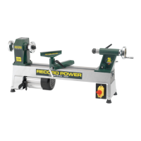
Attach the female cross brace to the upright column of the leg extension
using 2 M10 x 80 mm bolts, Fig 10.3.
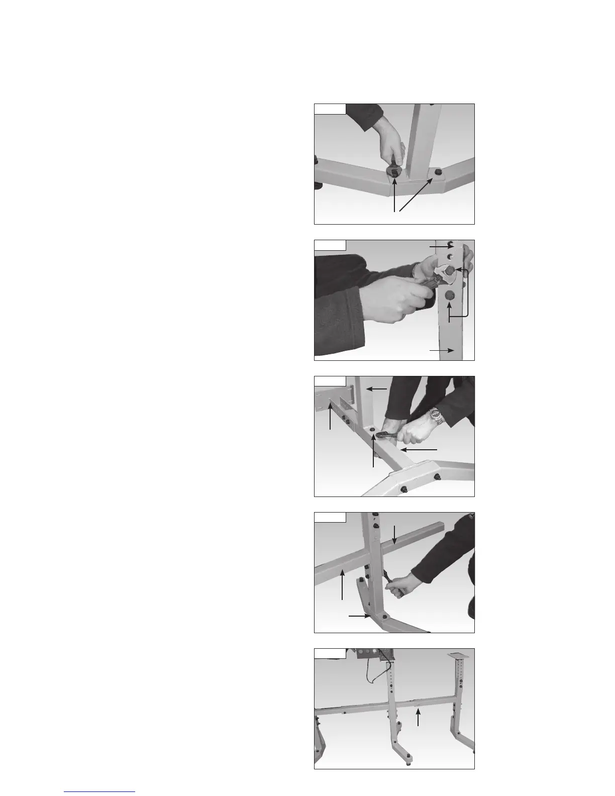
Attach the male cross brace to the main leg stand using the same bolts
which hold either the male or female cross brace in place on the main leg
stand, Fig 10.4. The Leg extension can be mounted to either side of the
main leg stand, depending on which way round the lathe was originally
attached to the main leg stand.
Set the distance between the main leg stand and the new leg extension so
that the bed extension can sit on the leg extension safely. Hold in place by
attaching the 2 M10 x 25 mm set screws in the female cross brace, Fig 10.5.
Fig 10.5
Main leg
stand
Main leg
stand
Hole for
set screw
Fig 10.4
Main leg
stand
Male cross brace
Fig 10.3
Upright
column
Female
cross brace
Upright
plinth
M10 x 80 mm
bolts
Base
Fig 10.1
M10 x 80 mm bolts
Fig 10.2
Upright column
Upright plinth
M10 x 80 mm bolts