18
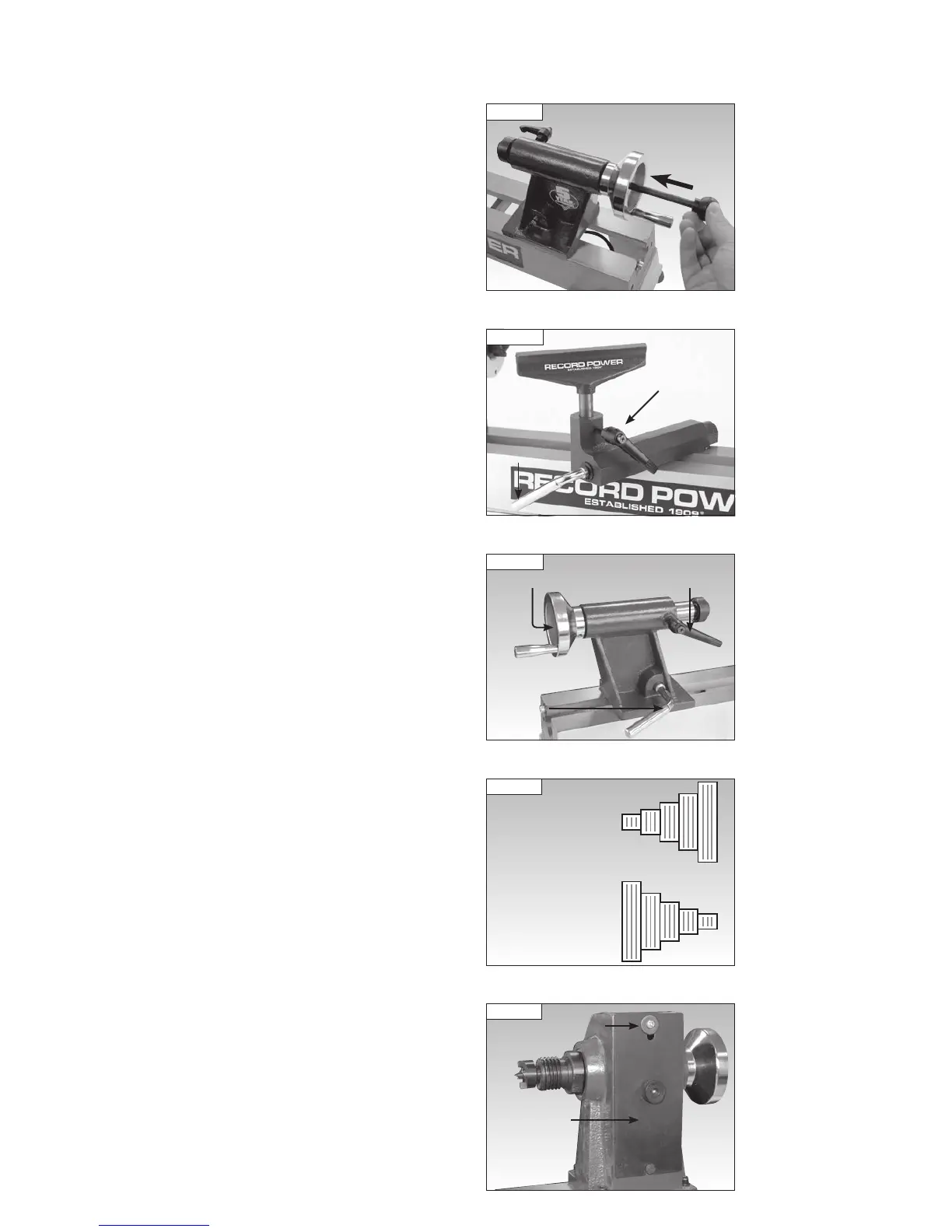
To remove the revolving centre from the tailstock spindle insert the knockout
bar into the hole in the centre of the tailstock hand wheel and give the
revolving centre a sharp knock to dislodge it from the tailstock, see Fig
11.11.
Adjusting the Tool Rest
To move the tool rest across the lathe bed, loosen the tool rest holder locking
lever, slide the tool rest holder to the desired position and tighten the locking
lever.
To adjust the height of the tool rest loosen the tool rest locking lever,
position as required and re-tighten, Fig 11.12.
Adjusting the Tailstock
Loosen the tailstock locking lever to move the tailstock along the lathe bed
to the desired position and tighten the lever, Fig 11.13.
To adjust the tailstock spindle position, loosen the tailstock spindle locking
lever and turn the hand wheel. When the tailstock spindle is in the desired
position, re-tighten the locking lever, Fig 11.13.
Adjustment of the Clamping Action of the Tool Rest Holder
and Tailstock
If the movement of the tool rest holder or tailstock is unsatisfactory, either
due to being too stiff and difficult to move or too easy to move and giving
inadequate locking, the clamping action can be adjusted. Please see the
Maintenance section of the manual for full details.
Changing the Spindle Speed
The DML250 features a 5 step pulley system. The drive belt must be
positioned on the corresponding pulleys as shown in Fig 11.14 to achieve
the speeds shown.
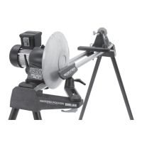
To access the spindle pulley, remove the cross head screw and washer from
the headstock cover using a cross head screwdriver (not supplied), and
remove the cover, Fig 11.15.
11. Operation
Fig 11.11
Fig 11.12
Tool rest
locking
lever
Tool rest
holder
locking
lever
Fig 11.13
Tailstock spindle
locking lever
Tailstock
locking
lever
Hand wheel
Fig 11.15
Headstock
cover
Screw and
washer
Fig 11.14
Pulley
Speed
Ranges
Spindle Pulley
Motor Pulley
450 rpm
980 rpm
1550 rpm
1940 rpm
2640 rpm