1
COUNT, DUAL COUNTER, RATE AND SLAVE DISPLAY
0.56" RED SUNLIGHT READABLE DISPLAY
VARIABLE INTENSITY DISPLAY
10 POINT SCALING FOR NON-LINEAR PROCESSES (PAXI)
FOUR SETPOINT ALARM OUTPUTS (W/Option Card)
RETRANSMITTED ANALOG OUTPUT (W/Option Card) (PAXI)
COMMUNICATION AND BUS CAPABILITIES (W/Option Card) (PAXI)
BUS CAPABILITIES; DEVICENET, MODBUS, AND PROFIBUS-DP
CRIMSON PROGRAMMING SOFTWARE (PAXI)
ETHERNET(W/ External Gateway) (PAXI)
NEMA 4X/IP65 SEALED FRONT BEZEL
GENERAL DESCRIPTION
The PAX Digital Input Panel Meters offer many features and performance
capabilities to suit a wide range of industrial applications. Available in three
different models, PAXC Counter/Dual Counter, PAXR Rate Meter and the PAXI
which offers both counting and rate in the same package. Refer to pages 4 - 5 for
the details on the specific models. The PAXC and PAXR offer only the Setpoint
Option, while the PAXI is the fully featured version offering all the capabilities
as outlined in this bulletin as well as a slave display feature. The optional plug-in
output cards allow the opportunity to configure the meter for present applications,
while providing easy upgrades for future needs.
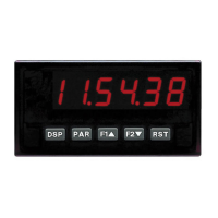
The meters employ a bright 0.56" LED display. The meters are available with
a red sunlight readable or standard green LED display. The intensity of the
display can be adjusted from dark room applications up to sunlight readable,
making it ideal for viewing in bright light applications.
The meters accept digital inputs from a variety of sources including switch
contacts, outputs from CMOS or TTL circuits, magnetic pickups and all
standard RLC sensors. The meter can accept directional, uni-directional or
Quadrature signals simultaneously. The maximum input signal varies up to 34
KHz depending on the count mode and function configurations programmed.
Each input signal can be independently scaled to various process values.
The Rate Meters provide a MAX and MIN reading memory with programmable
capture time. The capture time is used to prevent detection of false max or min
readings which may occur during start-up or unusual process events.
The meters have four setpoint outputs, implemented on Plug-in option cards.
The Plug-in cards provide dual FORM-C relays (5A), quad FORM-A (3A), or
either quad sinking or quad sourcing open collector logic outputs. The setpoint
alarms can be configured to suit a variety of control and alarm requirements.
Communication and Bus Capabilities are also available as option cards for
the PAXI only. These include RS232, RS485, Modbus, DeviceNet, and
Profibus-DP. Readout values and setpoint alarm values can be controlled
through the bus. Additionally, the meters have a feature that allows a remote
computer to directly control the outputs of the meter. With an RS232 or RS485
card installed, it is possible to configure the meter using Red Lion’s Crimson
software. The configuration data can be saved to a file for later recall.
A linear DC output signal is available as an optional Plug-in card for the PAXI
only. The card provides either 20 mA or 10 V signals. The output can be scaled
independent of the input range and can track any of the counter or rate displays.
Once the meters have been initially configured, the parameter list may be
locked out from further modification in its entirety or only the setpoint values
can be made accessible.
The meters have been specifically designed for harsh industrial environments.
With NEMA 4X/IP65 sealed bezel and extensive testing of noise effects to CE
requirements, the meter provides a tough yet reliable application solution.
SAFETY SUMMARY
All safety related regulations, local codes and instructions that appear in this
literature or on equipment must be observed to ensure personal safety and to
prevent damage to either the instrument or equipment connected to it. If
equipment is used in a manner not specified by the manufacturer, the protection
provided by the equipment may be impaired.
Do not use this meter to directly command motors, valves, or other actuators
not equipped with safeguards. To do so can be potentially harmful to persons or
equipment in the event of a fault to the meter.
MODEL PAX - 1/8 DIN DIGITAL INPUT PANEL METERS
Bulletin No. PAXICR-H
Drawing No. LP0548
Released 01/11
Tel +1 (717) 767-6511
Fax +1 (717) 764-0839
www.redlion.net
CAUTION: Risk of Danger.
Read complete instructions prior to
installation and operation of the unit.
CAUTION: Risk of electric shock.
3.80
1.95
.10
4.10
(2.5)
(96.5)
(49.5)
(104.1)
1.75
(44.5)
RSTDSP
PAR
F
1
F2
A
C
B
SP1 SP3
SP2
SP4
8.8.8.8.8.8
3.60 (91.4)
25
24
23
22
21
20
3
2
1
6
5
4
8
7
11
10
9
15
14
13
19
18
17
12
16
(44.5)
1.75
DIMENSIONS In inches (mm)
Note: Recommended minimum clearance (behind the panel) for
mounting clip installation is 2.1" (53.4) H x 5" (127) W.
C
US LISTED
U
L
R
51EB
IND. CONT. EQ.