14 | Installation
CAUTION: Check the manufacturer’s data for your battery and ensure that the Maximum voltage of
the Charging Profile you select does not exceed the manufacturer’s recommended maximum charging
voltage. If the Maximum voltage is too high for your battery type, select another Charging Profile.
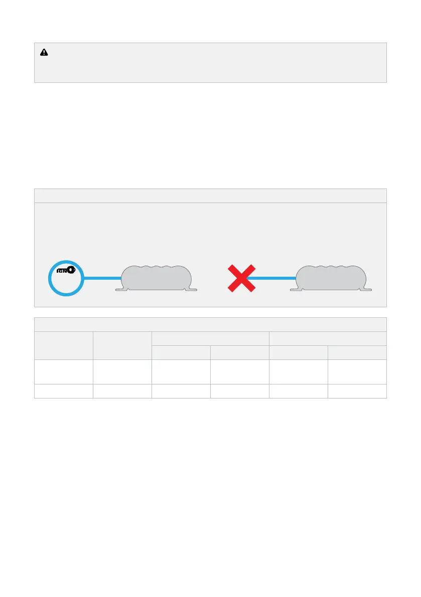
3.5 VEHICLE IGNITION INPUT — BLUE CABLE
The BLUE cable is required for vehicles with variable-voltage alternators to allow the BCDC1212T
to operate in Low Voltage Mode. Connect to a signal which is active when the engine is running.
For vehicles with fixed voltage alternators (standard alternator) the BLUE cable is not required and
the BCDC1212T will operate in Standard Voltage Mode. Leave the cable disconnected and apply
electrical tape over the end.
Figure 10: Connecting the BLUE cable
LOW VOLTAGE MODE
Connect the BLUE cable to D+ for Idle-stop
vehicles, or IGN for continuous Idle vehicles.
STANDARD VOLTAGE MODE
Leave and tape over the
disconnected BLUE cable.
Standard Low Voltage
Vehicle
Ignition
Blue Wire
Not
Connected
Blue Wire
OR
D+
Standard Low Voltage
Vehicle
Ignition
Blue Wire
Not
Connected
Blue Wire
OR
D+
Table 4: Setting the Vehicle Ignition Input
Input Mode
BLUE cable
connection
12 V Mode 24 V Mode
ON above OFF below ON above OFF below
Standard
Voltage
Not connected 12.9 V 12.7 V 25.8 V 25.4 V
Low Voltage Vehicle Ignition 12.0 V 11.9 V 24.0 V 23.8 V
If the Input Trigger (BLUE Cable) is connected to a signal other than the vehicle’s ignition signal,
charging will only occur while the signal is active AND the Low Voltage Turn ON and OFF
voltages in Section 1.6 (page 9) are valid. In some applications the BCDC could deplete the
start battery to 11.9V ±100mV or 23.8V ± 100mV for 12V and 24V vehicles respectively.