1
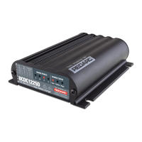
THE BCDC1225-XXX & BCDC1240-XXX
The BCDC1225-XXX / BCDC1240-XXX In-vehicle Battery Chargers feature technology
designed to charge your auxiliary batteries to 100%, regardless of their type or size.
Units that feature a Yellow wire include a Maximum Power Point Tracking (MPPT) solar
regulator. These units always take as much power from the unregulated Solar input as possible
before supplementing from Vehicle power input, up to the maximum rated power.
All In-vehicle Battery Chargers are suitable for all common types of automotive lead acid
batteries and LiFePO4 lithium type batteries.
WARNING & SAFETY INSTRUCTIONS
SAVE THESE INSTRUCTIONS - THIS MANUAL CONTAINS IMPORTANT SAFETY INSTRUCTIONS FOR THE BCDC1225-
XXX/BCDC1240-XXX BATTERY CHARGER RANGE.
DO NOT OPERATE THE BATTERY CHARGER UNLESS YOU HAVE READ AND UNDERSTOOD THIS MANUAL AND
THE CHARGER IS INSTALLED AS PER THESE INSTALLATION INSTRUCTIONS. REDARC RECOMMENDS THAT THE
CHARGER BE INSTALLED BY A SUITABLY QUALIFIED PERSON.
RISK OF EXPLOSIVE GASES:
WORKING IN VICINITY OF A LEAD-ACID BATTERY IS DANGEROUS. BATTERIES GENERATE EXPLOSIVE GASES
DURING NORMAL OPERATION. FOR THIS REASON, IT IS OF UTMOST IMPORTANCE THAT YOU FOLLOW THE
INSTRUCTIONS WHEN INSTALLING AND USING THE CHARGER.
1. The Battery Charger should not be used by persons (including children) with reduced physical, sensory or mental
capabilities, or lack of experience and knowledge, unless they are supervised or have been instructed on how to
use the appliance by a person responsible for their safety. Children should be supervised to ensure that they do
not play with the Battery Charger.
2. Do NOT alter or disassemble the Battery Charger under any circumstances. All faulty units must be returned to
REDARC for repair. Incorrect handling or reassembly may result in a risk of electric shock or fire and may void
the unit warranty.
3. Only use the Battery Charger for charging Standard Automotive Lead Acid, Calcium Content, Gel, AGM, SLI, Deep Cycle
or Lithium Iron Phosphate type 12V batteries.
4. If you need to replace your auxiliary battery, check the manufacturer’s data for your battery and ensure that the
‘Maximum’ voltage of the profile you select does not exceed the manufacturer’s recommended maximum charging
voltage. If the ‘Maximum’ voltage is too high for your battery type, please select another charging profile.
5. Check the manufacturer’s data for your battery and ensure that the ‘Continuous Current Rating’ of the charger does
not exceed the manufacturer’s recommended maximum charging current.
6. When using the Battery Charger to charge a Lithium Iron Phosphate battery, only batteries that feature an inbuilt
battery management system featuring inbuilt under and over voltage protection and cell balancing are suitable.
7. The Battery Charger is not intended to supply power to a low voltage electrical system other than to charge a battery.
8. Cable and fuse sizes are specified by various codes and standards which depend on the type of vehicle the Battery
Charger is installed into. Selecting the wrong cable or fuse size could result in harm to the installer or user and/or
damage to the Battery Charger or other equipment installed in the system. The installer is responsible for ensuring
that the correct cable and fuse sizes are used when installing this Battery Charger.
9. NEVER smoke or allow a spark or flame in vicinity of battery or engine. This may cause the battery to explode.
PERSONAL SAFETY PRECAUTIONS
10. To assist with the safe operation and use of the Battery Charger when connected to the battery:
a) Wear complete eye protection and clothing protection. Avoid touching eyes while working near a battery.
b) If battery acid contacts your skin or clothing, remove the affected clothing and wash the affected area of your skin
immediately with soap and water. If battery acid enters your eye, immediately flood the eye with running cold water
for at least 10 minutes and seek medical assistance immediately.
SPECIFICATIONS
Part Number BCDC1225-XXX BCDC1240-XXX
Continuous Current Rating 25A 40A
Vehicle Input Fuse Rating
40A (Not Supplied)
REDARC FK40 recommended
60A (Not supplied)
REDARC FK60 recommended
Output Fuse Rating
Output Power 375W 600W
Vehicle Input Voltage Range
*1
9-32V
Solar Input Voltage Range
*1
9-32V (unregulated only)
Output Battery Type Standard Lead Acid, Calcium content, Gel, AGM or LiFePO
4
type only
Charging Profile A B C Li
- Maximum Voltage
*1
14.6V 15.0V 15.3V 14.5V
- Float Voltage
*1
13.3V 13.6V
No Load Current <100mA
Standby Current <8mA
Operating Temperature -15°C to 80°C / 5°F to 175°F
Minimum O/P Battery Volts 0.1V
Weight 0.9kg / 2lbs
Dimensions 165x120x37mm
Warranty 2 years
Standards ECE Reg. 10
*1
Voltages Specified are ±100mV
TURN ON/OFF THRESHOLDS
Input 12V Vehicle Input 24V Vehicle Input Solar
Input Trigger
Settings
Standard
Low
Voltage
Standard
Low
Voltage
N/A
Input
Open Circuit
Low voltage
conditions *
2
Turn ON
ABOVE
13.2V 12.0V 26.4V 24.0V 9.0V
Turn OFF
BELOW
12.7V 11.9V 25.4V 23.8V 9.0V
Input
Loaded Low
voltage
conditions*
3
Turn OFF instantly
BELOW
8.0V 16.0V 9.0V
Turn OFF after 20s
BELOW
9.0V 18.0V N/A
Input
Over voltage
shutdown
Turn ON
BELOW
15.5V 32V
Turn OFF instantly
ABOVE
16.0V 32.5V 33.0V
Turn OFF after 20s
ABOVE
15.6V 32.1V N/A
Output
Under voltage
shutdown *
1
Shutdown if Output Battery < 0.1V
*
2
Tested every 100 Seconds.
*
3
Constantly tested.
INSTALLATION
Mounting the Unit
The charger is suitable for mounting in the cabin of the vehicle only and should not
be mounted in a location exposed to water or dust ingress e.g. under bonnet or
vehicle exterior. The unit will operate optimally below 55°C/130°F with good airflow.
At higher temperatures the unit will de-rate output current up to 80°C/ 175°F at
which point the unit will turn OFF.
It is important to ensure the charger is mounted as close as possible to the battery
being charged (auxiliary battery). Lithium type (LiFePO
4
) batteries are not suitable for
engine bay installations.
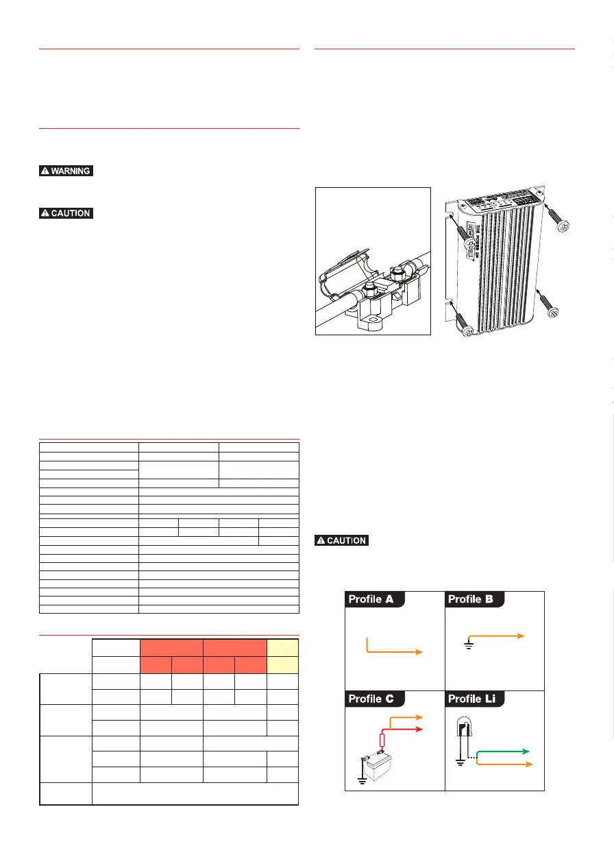
The charger should be mounted in any orientation (so that the front decal is visible)
using the 4 mounting tabs provided on the heatsink using Zinc plated, G4.6 M5
Screws.
A single fuse and holder
setup from the Fuse Kits
available from REDARC.
Part number FK40 (40A)
or FK60 (60A).
Fusing
REDARC recommend using MIDI style bolt down fuses as they ensure a low resistance
connection. The REDARC FK40 and FK60 fuse kits are recommended.
Blade type fuses are not recommended as they can result in a high resistance
connection which causes excess heat and may damage the fuse holder and/or the
wiring.
Self-resetting circuit breakers are not recommended as they may trip prematurely due
to the heat generated by the current flowing through the wires.
Charge Profile Selection (ORANGE Wire)
The ORANGE wire is used to select the Maximum output voltage. This is achieved by
connecting in the following way:
To select Profile A leave the ORANGE wire disconnected. This will set the Maximum
voltage to 14.6V.
To select Profile B connect the ORANGE wire to Common Ground. This will set the
Maximum voltage to 15.0V.
To select Profile C connect the ORANGE wire to the RED wire (Input source positive).
This will set the Maximum voltage to 15.3V.
To select the Li Profile connect the ORANGE wire to the GREEN wire (LED output).
This will set the charger to Lithium mode.
Check the manufacturer’s data for your battery and ensure that the Maximum voltage of the
profile you select does not exceed the manufacturer’s recommended maximum charging
voltage. If the Maximum voltage is too high for your battery type, please select another
charging profile.
Not
Connected
Orange Wire
Orange Wire
Orange Wire
Red Wire
Input
Source
Positive
Midi
Fuse
Green Wire
Optional
LED
Orange Wire
INSTALLATION
Input Trigger Settings (BLUE Wire)
The BLUE wire is used to switch the vehicle input turn ON trigger mode between:
• Standard trigger (for fixed voltage or temperature compensating alternators)
• Low Voltage trigger (for variable voltage or Smart Alternators)
Standard Low Voltage
Vehicle
Ignition
Blue Wire
Not
Connected
Blue Wire
Input Mode Blue Wire Connection
12V Mode 24V Mode
ON above OFF below ON above OFF below
Standard Not Connected 13.2V 12.7V 26.4V 25.4V
Low Voltage Vehicle Ignition 12.0V 11.9V 24.0V 23.8V
Cable sizing
Below is a table outlining the required cable size for a given cable install length.
Please refer to this table for Vehicle Input, Solar Input, Ground and Battery Output cable
thickness requirements. Always choose a wire cross sectional area equal to or greater
than what is specified below.
Part Number Cable Install Length
(m) (ft)
Recommended Wire
Cross Section (mm²)
Closest
(BAE, B&S, AWG)
BCDC1225-XXX
Variants
1 - 5 3 - 16 7.71 8
5 - 9 16 - 30 13.56 6
BCDC1240-XXX
Variants
1 - 5 3 - 16 13.56 6
5 - 9 16 - 30 20.28 4
Cable and fuse sizes are specified by various codes and standards which depend on the type
of vehicle the Battery Charger is installed into. Selecting the wrong cable or fuse size could
result in harm to the installer or user and/or damage to the Battery Charger or other equipment
installed in the system. The installer is responsible for ensuring that the correct cable and fuse
sizes are used when installing this Battery Charger.
Typical Setup
12V or 24V
Start Battery
Bank
Fuse*
12V Solar Panel
Array
(Unregulated)
24V
INPUT
Fuse*
Optional LED
All ground points must
be connected to chassis
earth.
Auxiliary
Battery
Charging Profile Select
Red
Blue
Orange
Black
Brown
Green
12V
INPUT
OR
Yellow
AND
SOLAR
INPUT
Standard
Trigger Settings
Low Voltage
Trigger Settings
Load
Fuse
Loads
to Vehicle
Ignition
Leave
unconnected
Figure 1 - Typical Lead Acid type Setup
NOTE: BCDC1225-002/BCDC1240-002 will only accept input from an unregulated solar panel.
24V
INPUT
Fuse*
Optional LED
All ground points must
be connected to chassis
earth.
Auxiliary
Battery
Fuse*
Join GREEN and ORANGE
for LiFePO
4
Charging
Red
Blue
Orange
Black
Brown
Green
12V
INPUT
OR
Yellow
AND
SOLAR
INPUT
Low Voltage
Trigger Settings
to Vehicle
Ignition
Load
Fuse
Loads
Low Voltage
Disconnect
Standard
Trigger Settings
Leave
unconnected
12V or 24V
Start Battery
Bank
12V Solar Panel
Array
(Unregulated)
Figure 2 - Typical LiFePO
4
Setup

 Loading...