MECHANICAL INSTALLATION
Do not apply power supply before carry out the following operations.
The off-centre position of the rear connector housing only allows
MOSAIC M1S COM to be housed on the right side of any other MOSAIC
expansion module.
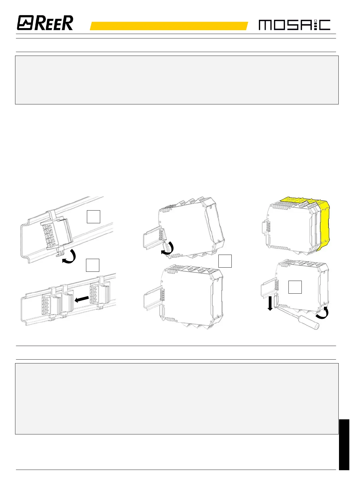
1. Fix to the Omega DIN 35mm (EN 5022) the same number of "MSC" 5-pole rear panel
connectors as the number of units to be installed (hooking them at the top first).
2. Connect between them the connectors just mounted.
3. Fasten the units to the rail, arranging the contacts on the base of the unit on the
respective connector. Press the unit gently until you feel it snap into place.
4. To remove a unit, use a screwdriver to pull down the locking latch on the back of the
unit; then lift the unit upwards and pull.
ELECTRICAL CONNECTIONS
Install safety units in an enclosure with a protection class of at least IP54.
The supply voltage to the units must be 24Vdc 20% (PELV, in
compliance with the standard EN 60204-1 (Chapter 6.4)).
Do not use the MOSAIC to supply external devices.
The same ground connection (0VDC) must be used for all system
components.