Rev 3.1 14 | P a g e
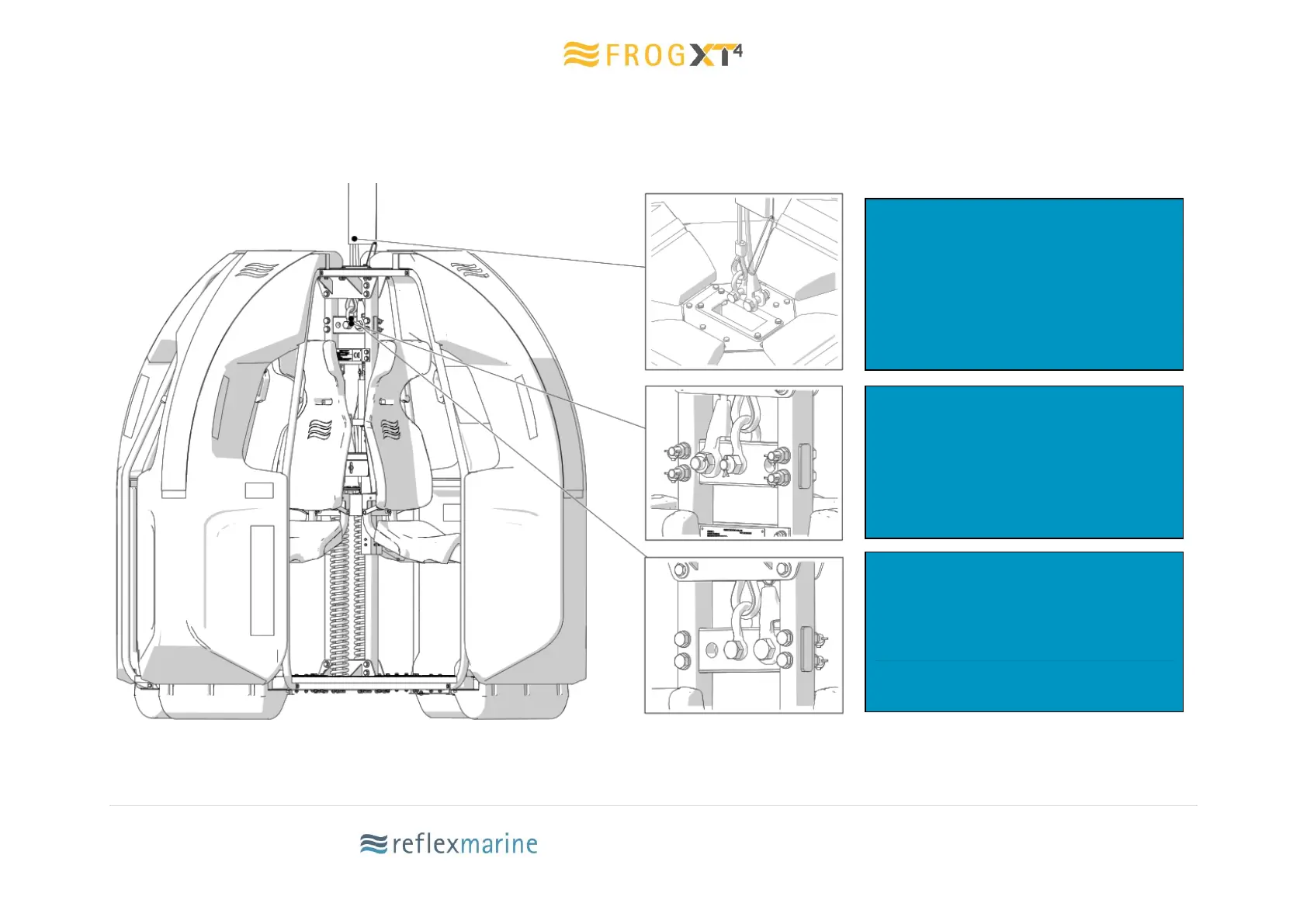
3.8 Lifting Assembly Connection
Figure 3 Lifting Assembly
Lifting assembly is fitted to the FROG-XT4
by initially lowering it through the letter
box opening at the top of the carrier.
The lifting assembly is fitted with two
different terminations. The main leg is
fitted with a bow shackle and the back-up
leg is fitted with a spelter socket.
in the load plate and the backup leg
connects to either the far right or far left
hole.
A handling line can then be fitted to the
 Loading...