— English EEHR Electric screw-in heating element — 18.05.2018
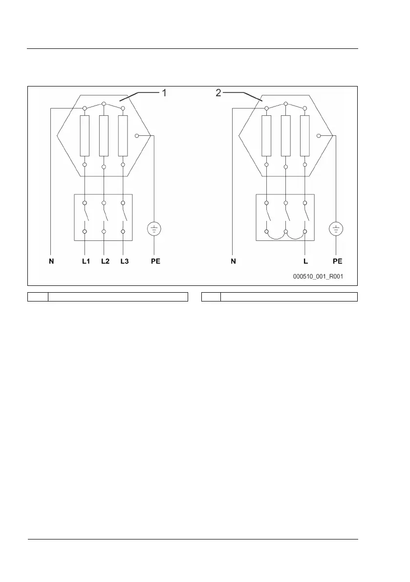
1 Three-phase connection, 400 V (as supplied) 2 Single-phase connection, 230 V (max. 3 KW)
Realising the electrical connection
These prerequisites must be met for electrical connections:
• Connections are to be established according to electro-technical regulations and local rules.
• The supply voltage must match the voltage indicated on the nameplate.
• Electrical connections are to be realised according to the terminal plan.
• Use suitable installation material.
– Select the conductor cross-sections and fusing according to the electrical power used by the device.
• The storage tank must be appropriately earthed.
Proceed as follows:
1. Switch off the device.
2. Secure the facility against unintended reactivation.
3. Undo the four screws on the device protective cover.
4. Remove the protective cover.
5. Thread the connecting cable through the previously fitted cable gland.
6. Connect the conductors according to the terminal plan.
7. Ensure the proper connection of the protective conductor
8. Position the protective cover.
9. Fasten the protective cover with the screws.
– If necessary, ensure sufficient sealing according to degree of protection IP54.
– Tighten the screws of the protective cover. Only the original screws and washers may be used.
– Remove the information sheet which is supplied contained within the connection area and keep it together with this installation manual.
10. Tighten the cap of the cable gland to secure the cable strain relief device and to achieve the nominal IP rating.
11. Check the protective cover is securely seated.
12. Reactivate the system.
The electrical connection is completed.