Fillcontrol Auto Make-up and degassing — 06.07.2016 - Rev. B English —
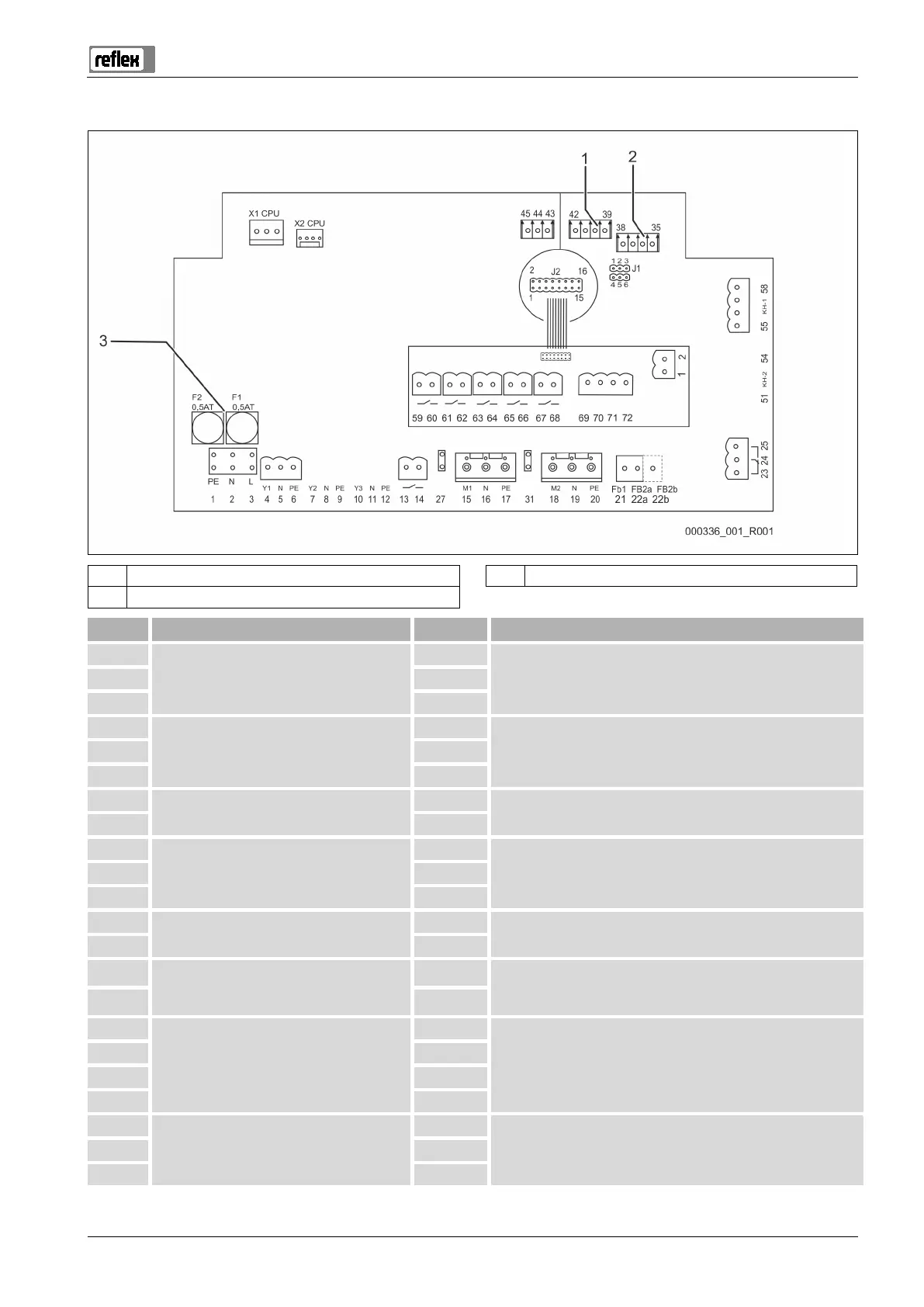
6.4.1 Control cabinet terminal plan
1 Pressure 3 Fuses
2 Level
X0/ 1
Supply (230 V)
L
User supplied
• Wiring at the terminal block next to the fuses
X0/ 2 N
X0/ 3 PE
4
Makeup (230 V)
Y1
Is installed
• Fillcontrol Auto 2PS
5 N
6 PE
13
Floating signal contact 1
User supplied, optional
14
23
Group message (floating)
NC
User supplied, optional 24 COM
25 NO
69
Contact water meter (system separator
tank)
+24 V DC
Factory
70 E2
43
Contact water meter (option)
+24 V DC
Is installed
• Fillcontrol Auto 2PS
44 E1
39
Pressure transducer
+18 V
Is installed
40 GND
41 AE
42 PE (shield)
15
Pump 1 (230 V)
M1
Is installed 16 N
17 PE