Vacuum spray degassing — 28.08.2019 - Rev. B
English — 15
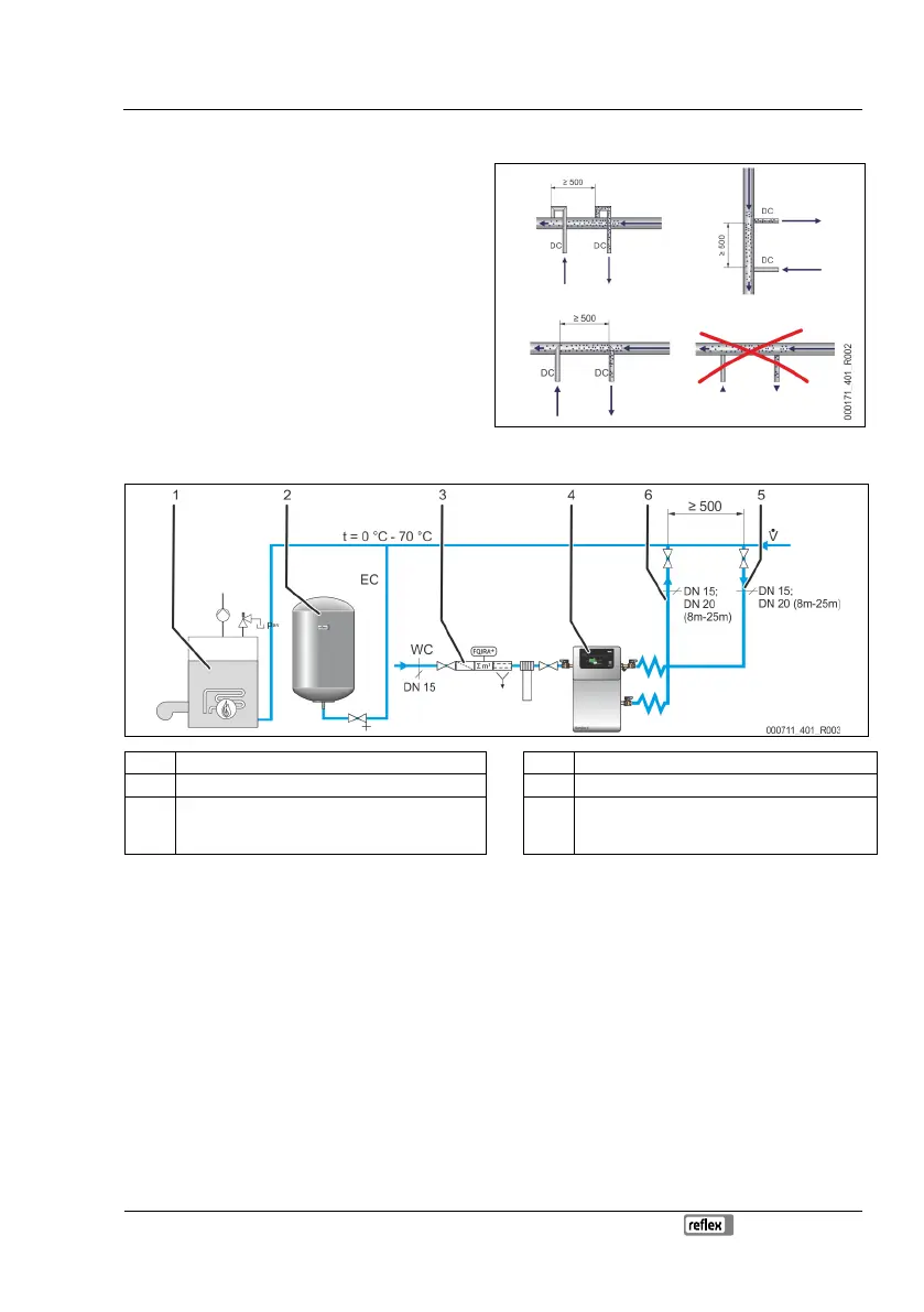
6.3.3 Degassing line to the system
Installation detail of the "DC" degassing line
Install the "DC" degassing lines as follows:
Prevent an overload of the "ST" dirt trap in the device
caused by coarse dirt.
Install the gas-rich degassing pipe “DC” upstream of the
gas-poor degassing pipe (when viewed in the system
flow direction).
Preferably install on the return side of the facility
system.
– The water temperature must be in the range of 0
°C – 70 °C to ensure sufficient degassing
capacity.
Device installation in a heating system – Pressure maintenance with bladder "MAG" expansion vessel
1 Heating system 4 Device
2 Bladder expansion vessel 5 "DC" degassing line (gas-rich water)
3 For optional equipment and accessories, see
chapter 4.5 "Optional equipment and accessories"
on page 10
6 "DC" degassing line (degassed water)
Proceed as follows:
• Connect the "DC" degassing lines in the "V" main volume flow of the facility system.
• The device requires two "DC" degassing lines to the facility system.
– One degassing line for the gas-rich water from the facility system
– One degassing line for the degassed water back to the facility system.
• Fit the degassing lines near the "EC" expansion line.
– This ensures stable pressure conditions.
• Install the device near the "MAG" expansion vessel.
– This ensures pressure monitoring of the expansion vessel.
– Set the "Magcontrol" operating mode at the device controller.
Ensure the integration with the "V“ main flow volume. in particular in switching variants with hydraulic
switching points and return admixtures.
– For switching and make-up variants, see chapter 6.4 "Switching and make-up variants" on page 16 .