Vacuum spray degassing — 28.08.2019 - Rev. B
English — 19
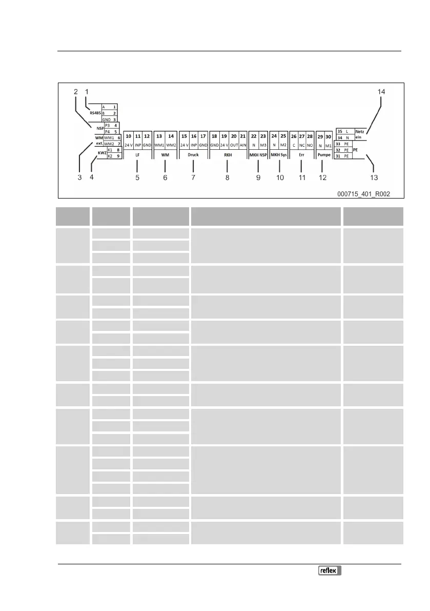
6.5.1 Terminal diagram
1
1 GND
RS485 interface User, optional 2 A
3 B
2
4 P3 External make-up request.
• With Levelcontrol setting. Input 230 V signal via
L+N.
User, optional
5 P4
3
6 WM1
Insufficient water external - digital input. User, optional
7 WM2
4
8 K1
Contact water meter User, optional
9 K2
5
10 24 V
Conductivity - analogue input 4-20 mA User, optional
12 GND
6
13 WM1
--- ---
14 WM2
7
15 24 V
Pressure sensor - Analogue input 4-20 mA Factory 16 INP
17 GND
8
18 GND
--- ---
19 24 V
20 OUT
21 AIN
9
22 N
Motorized ball valve on the make-up side Factory
23 M3
10
24 N
Motorized ball valve on the system side Factory
25 M2