Description of the device
— English Vacuum spray degassing — 28.08.2019 - Rev. B
4.2 Identification
The nameplate provides information about the manufacturer, the year of manufacture, the manufacturing number and the
technical data.
Information on the type plate
Serial No. Serial number
min. / max. allowable pressure P Minimum/maximum permissible pressure
max. continuous operating temperature Maximum temperature for continuous operation
min. / max. allowable temperature / flow temperature TS Minimum / maximum permissible temperature / TS flow
temperature
Year built Year of manufacture
min. operating pressure set up on shop floor Factory set minimum operating pressure
at site Set minimum operating pressure
max. pressure saftey valve factory - aline Factory set actuating pressure of the safety valve
at site Set actuating pressure of the safety valve
4.3 Function
The device is suited for the degassing of water from the plant and make-up water. It removes up to 90 % of the dissolved gases
from the water. The degassing operation uses timer-controlled cycles.
A cycle comprises the following phases:
1. Pump down to create a vacuum
The pump “PU” creates a vacuum in the spray pipe. The “DC” feed (during “WC” make-up degassing) to the vacuum spray
tube “VT” is open. Gas-rich water is sprayed into the spray tube via a nozzle. The system is set up so that the pump draws
more water from the spray tube than can flow through the nozzle.
2. Injection
The "DC“ feed of gas-rich water from the system to the "VT" vacuum spray tube is opened. Depending on the requirement,
partial flows of the gas-rich system water and the make-up water are atomised in the vacuum spray tube via the "DC" and
"WC" lines. The large surface of the atomised water and the gas saturation headway to the vacuum result in a degassing of
the water. The "PU" pump returns degassed water from the vacuum spray tube to the system where it again begins to
dissolve gases. Here it is able to dissolve gases again.
3. Discharge
The "PU" pump shuts off. The system continues to inject and degas water in the "VT" vacuum spray tube. The water level in
the vacuum spray pipe rises. The gases separated from the water are discharged via the "DV" degassing valve.
4. Idling time
When the gas has been discharged, the device will remain idling until the next cycle is started.
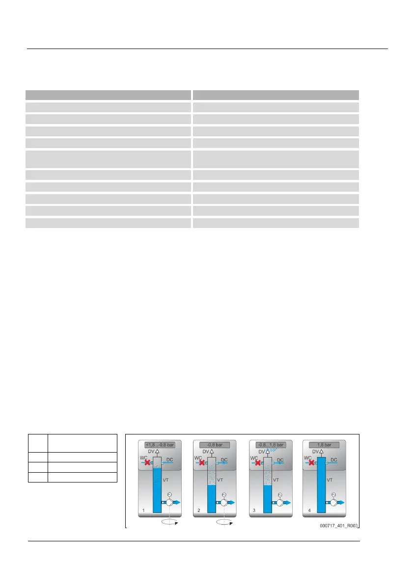
Sequence of a degassing cycle in the vacuum spray pipe"VT"
Cooling water system ≤ 30 °C, System pressure 1.8 bar, "DC" system degassing in operation, "WC" make-up degassing closed.
1 Pump down to create a
vacuum
2 Injection
3 Discharge
4 Idling time