Designation
Terminal
Contactor
terminal
Signal Remarks
Pump 2
18 M2
(230 V)
19 N Is connected
20 PE
Pump 1 (2)
6K1 / 2 U
(400 V)
6K1 / 4 V
6K1 / 6 W
X0 / 6 PE
Pump 2
6K5 / 2 U
(400 V)
6K5 / 4 V
6K5 / 6 W
X0 / 7 PE
Overfl ow solenoid
valve 1 (5)
7Y2
8N
Is connected
9PE
Overfl ow solenoid
valve 2
10 Y3
Is connected11 N
12 PE
Motorised ball
valve 1
55 GND
56 +24 V
Supply
57 0 - 10 V Manipulated variable
58 0 - 10 V Feedback
Motorised ball
valve 2
51 GND
52 +24 V
Supply
53 0 - 10 V Manipulated variable
54 0 - 10 V Feedback
RS-485
The interface is positioned at the display board in the bottom
interface
left corner of the control box door. Description → p. 24
reflex ’variomat’
Assembly
14
Designation
Terminal Signal Remarks
Supply 1 PE
’variomat 1’ line wired with a shock-proof plug(230 V) 2 N
3L
Make-up (4) 10 Y1
(230 V) 11 N
12 PE
Common message 13 COM
(fl oating) 14 NC
15 NO
Level gauge 19 PE
Screen
(pressure cell) 20 - level Signal
(8) 21 + level + 18 V
Pressure
transducer (4)
22 PE
Screen
23 - pressure Signal
24 + pressure + 18 V
Pump 1 (2) 4 PE
(230 V) 5 N
6M1
Overfl ow solenoid
valve 1 (5)
7Y2
8N
Is connected
9PE
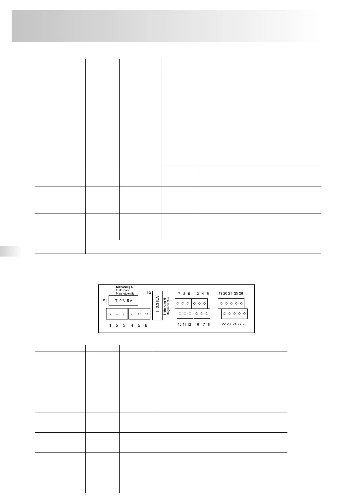
Overview of the wiring diagram on the circuit board - ’variomat 1’