Note:
Please check the delivery for completeness and damage immediately upon receipt of
the goods! Transport damage must be reported immediately!
The scope of delivery is described on the delivery note and the contents
indicated on the cardboard box.
Main components required for proper functioning of the system (→ see also p. 3)
’variomat’ control unit on pallet,
connection set connection set in a separate cardboard box, foil pocket
with operating instructions and electrical circuit diagram
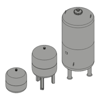
VG basic vessel with add-on parts in a foil bag at the vessel foot
Possible options
’variomat’ VF secondary vessel with flexible hose set and add-on parts
in a foil bag at the vessel foot
VW thermal insulation
reflex ’fillset’ (with standard or contact water meter)
Add-on module
Bus modules
Communication module (control panel for remote control)
Choose the installation site. Please note that the control unit and the VG/VF
vessels must be placed one next to the other on the same level.
Requirements for the installation room:
− Frost-free, well-ventilated room; room temperature > 0 to max. 45°C
− No unauthorised access
− Level floor with adequate load-bearing capacity and drainage facility
− Filling connection DN 15, according to DIN 1988 P 4; max. normal
pressure 6.0 bar
− Electrical connection to 230 V~, 50 Hz, 16 A with upstream ground fault circuit
interrupter: tripping current 0.03 A
}
reflex ’variomat’
Assembly
6
Scope of delivery
Installation site