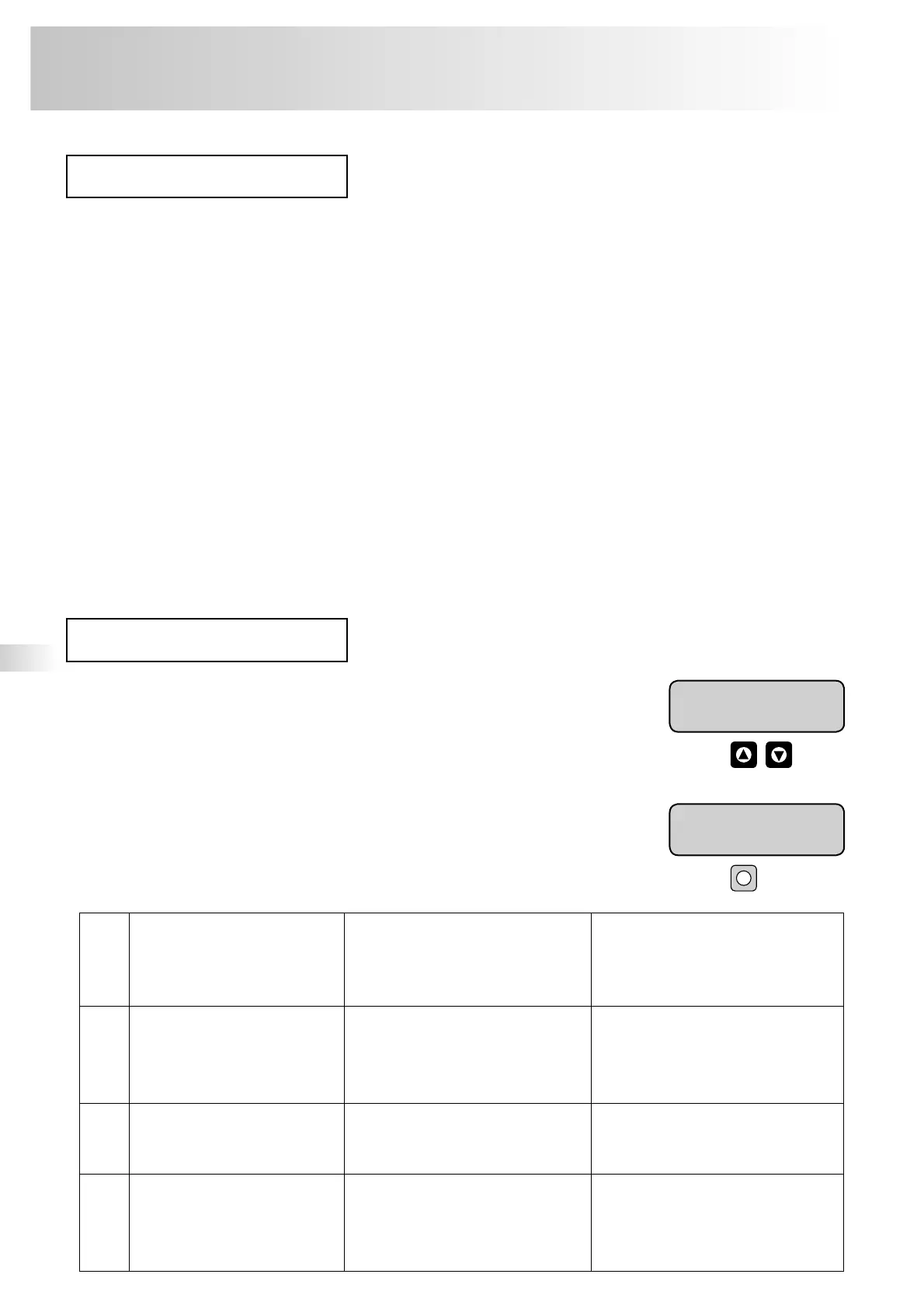
Messages are shown as clear text in the message line of the display using the codes
specified below. If there are a number of messages you can use the “up”/“down” control
buttons to scroll through them.
All messages/faults are automatically reset if they can be resolved. They
are, however, recorded in the error memory and can be retrieved from there
(→ p. 22).
The messages Er 01, Er 04, Er 08, Er 09 and all errors related to water make-up must be
acknowledged manually using the “quit” button since the error cause needs to be examined
in these cases.
The messages can only be acknowledged if the error is no longer present.
4% 1.6 bar
Water def. 02.1
7% 1.6 bar
Make-up time 06
The following information is made available using this interface:
– Continuous information about pressure and level
– Information about the operating statuses of the pumps
– Information about the operating statuses of the overflow solenoid valves
– Information about the operating status of the make-up solenoid valve
– Information about the aggregated value of the contact water meter
– Information about all messages
– Information from the error memory
Connection of the interface with the primary control centre or similar
– The interface is positioned at the display board in the bottom left corner of the control box door. A four-pin plug (plug-
type PCB terminal, grid 3.81 mm, 4-pin, type 8813B/04OB) is required for connecting the interface. The plug can be
obtained from Reflex Service.
– The interface should be connected using a screened cable twisted or stranded together in pairs, for example LJYCY
(TP), 4 x 2 x 0.8 (max. overall bus length = 1000 m).
– When using a control centre or similar equipped with an RS-232 interface and not an RS-485 interface, an appropriate
interface converter must be used.
– When using the communication module (optional) the interface is used to connect the communication module.
The protocol for the RS-485 interface can be requested from Reflex Service if required.
quit
reflex ’variomat’
Operation
24
RS-485 interface
Messages
ER
code
Type of error Cause of error Troubleshooting/
remedy
01
Min. pressure
p0 fallen below
(alarm)
– Water loss in the system
–
Pump fault, for example pump motor
protection triggered
– Fix leak
– Acknowledge error (“quit” button)
02.1
02.2
Dry-running protection during
operation
of pump 1
of pump 2
only with variomat 2-2/…
– Water make-up not connected
– Dirt trap in make-up line blocked
– Make-up solenoid valve not opening
– Large amounts of gas in the system
– Manually make-up water into VG basic
vessel through the hose
– Clean dirt traps
– Check the WM solenoid valve via “hand”
– Bleed the system manually
03
Max. water level exceeded – Water make-up defective
– Make-up water manually
– Leak in on-site heat exchanger
– VG basic vessel too small
– Release water
– Check heat exchanger
– Check vessel size
04.1
04.2
Pump/pumps fault for example
motor protection triggered
Fault in pump 1
Fault in pump 2
only with variomat 2-2/...
(alarm)
– Pump/pumps stuck
– Motor/motors defective
– 10 A screw fuse defective
– Motor protection (Klixon) triggered if
connected
– Use a screwdriver to crank the motor axle
via the fan wheel (required after a lengthy
downtime)
– Acknowledge error (“quit” button)
–
Notify Reflex Service