Variomat Touch — 09.2020 - Rev. A
*Addition of 0.2 bar recommended, no addition in extreme cases
Note!
Avoid dropping below the "P
0
"minimum operating pressure. Vacuum,
vaporisation and cavitation are thus excluded.
8.3 Modifying the controller's start routine
Note!
For handling the operator panel see chapter 10.1 "Operator panel" on
page 19
The start routine is used to set the parameters for device commissioning. It
commences with the first switching on of the controller and can only be set once.
The following parameter changes or checks are carried out from the customer
menu, see chapter 10.3 "Configuring settings in the controller" on page 19 .
A three-digit PM code is assigned to the setting options.
Start of the start routine
Remember: Prior to installation and commissioning,
read the operating manual!
Set the minimum operating pressure P
O
, see
chapter 8.2 "Variomat switching points" on page 15 .
Select the primary vessel nominal volume
Null balancing: The primary vessel must be empty!
The system checks whether the signal from the level
sensor matches the selected primary vessel
End of the start routine. The stop mode is active.
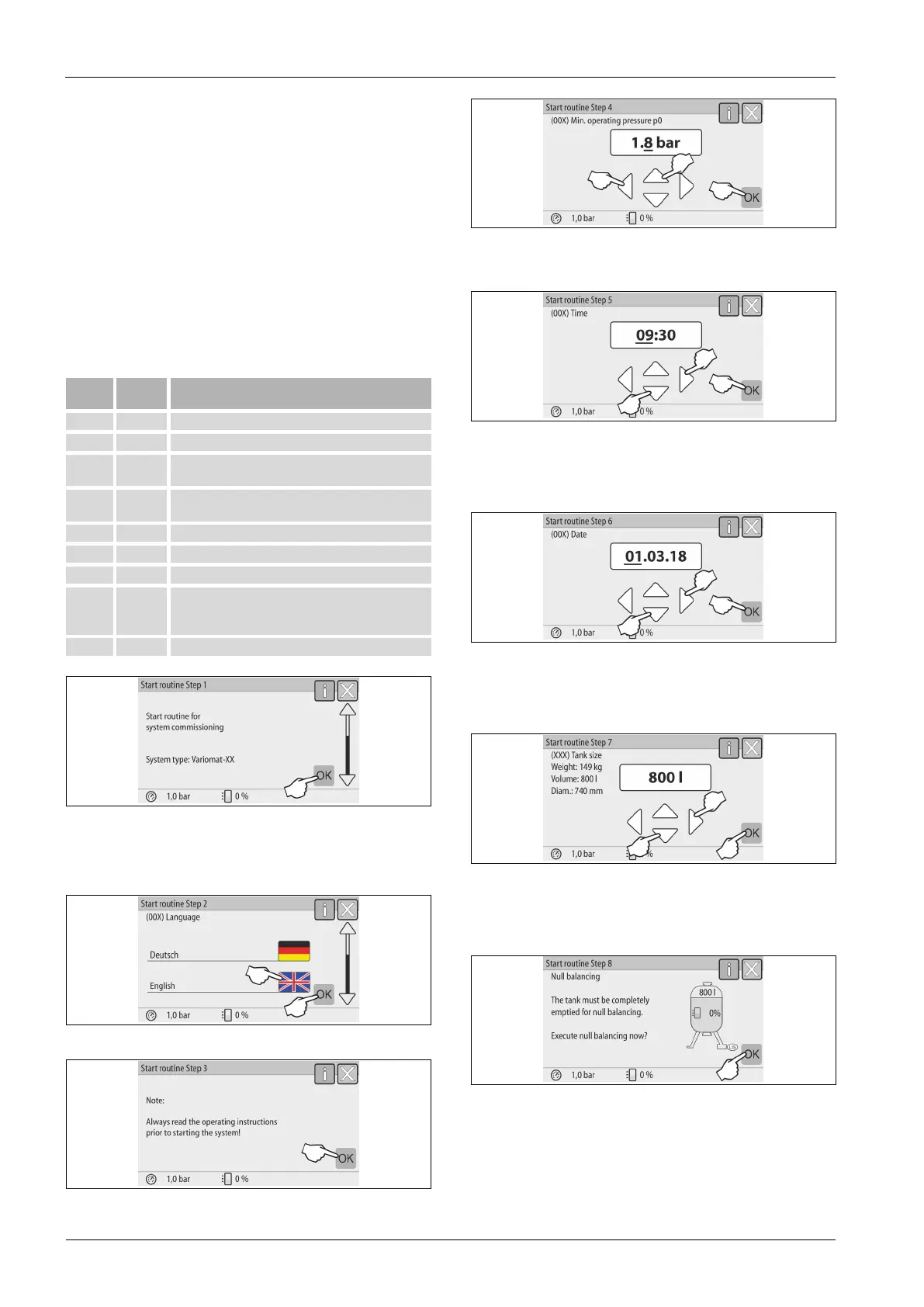
The system automatically displays the first page of the start routine when you
switch on the device for the first time:
1. Press "OK“.
– The start routine moves to the next page.
2. Select the required language and conform your entry with "OK".
3. Prior to commissioning, read the operating manual in full and check for
proper assembly.
4. Select the calculated minimum operating pressure and conform with "OK".
– For calculation of the minimum operating pressure, see chapter 8.2
"Variomat switching points" on page 15 .
5. Set the time. The time of an alarm will be stored in the controller's fault
memory.
– Use the "Left" and "Right" buttons to select the display value.
– Use the "Up" and "Down" buttons to change the display value.
– Confirm your entries with "OK".
6. Set the date. The date of an alarm will be stored in the controller's fault
memory.
– Use the "Left" and "Right" buttons to select the display value.
– Use the "Up" and "Down" buttons to change the display value.
– Confirm your entries with "OK".
7. Select the size of the primary vessel.
– Use the "Up" and "Down" buttons to change the display value.
– Confirm your entries with "OK".
– For the primary vessel data, see the name plate or see chapter 6
"Technical data" on page 8 .
– The controller checks whether the level measuring signal matches
the dimensional data of the primary vessel. The primary vessel must
be fully emptied, see see chapter 7.3.6 "Fitting the level sensor" on
page 11 .
8. Press "OK“.
– Null balancing is executed.
– If null balancing is not successfully completed, you cannot
commission the device. In this case, please contact Customer
Service, see chapter 13.1 "Reflex Customer Service" on page 26 .