26 | Regency
®
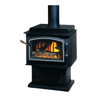
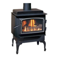
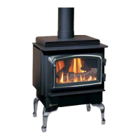
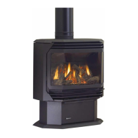
CLASSIC C34-10 Direct Vent Freestanding Gas Stove
|
26
installation
CATHEDRAL CEILINGS
Round Support (RDS) & Square
Support (SQS)
If your home has a cathedral ceiling (no attic space
between the ceiling and the roof), install the chimney
and support as follows.
1. Situate the chimney in a convenient location as
near as possible to the appliance outlet. Cut
and frame a hole in the roof for the support. The
sides of this hole must be vertical with 1-1/4"
clearance.
2. Place the support in the opening. Lower it to the
correct height as determined by the table and
diagram below.
Using a level, make sure the support is vertical.
If the support extends above the roof, cut
it ush with the top of the roof. Nail the
support to the frame opening using (8. 3"
spiral nails or #8 x 1-1/2" screws.
Note: If you are using a 6" square support
you may nd it difcult to screw it
in place because it is fairly small
inside.
Simpson Dura-Vent has provided angle
brackets with this support which can be
screwed to the outside of the support
box and nailed to surrounding framing as
required. Use a minimum of four #8 x 1/2"
screws per bracket. In some cases these
brackets may need to be trimmed (e.g.:
to t under a ashing). Place the Finish
Collar around the support and fasten it to
the ceiling using the screws provided.
3. Use appropriate roof ashing. Place the
ashing under the upper shingles and on top
of the lower shingles approximately half of
the ashing should be under the shingles.
4. Assemble the desired lengths of Black Pipe
and Elbows necessary to reach from the
appliance adaptor up through the support
box and ashing to proper height as per
Diagram 12, local codes or "Exterior Vent
Terminal Locations" section. Ensure that
all pipe and elbow connections are in their
fully twist lock position.
5. Ensure vent is vertical and secure ashing to
the roof with roong nails. Slide the storm
collar over the pipe section and seal with a
mastic.
6. Twist lock the vent cap on to the last section.
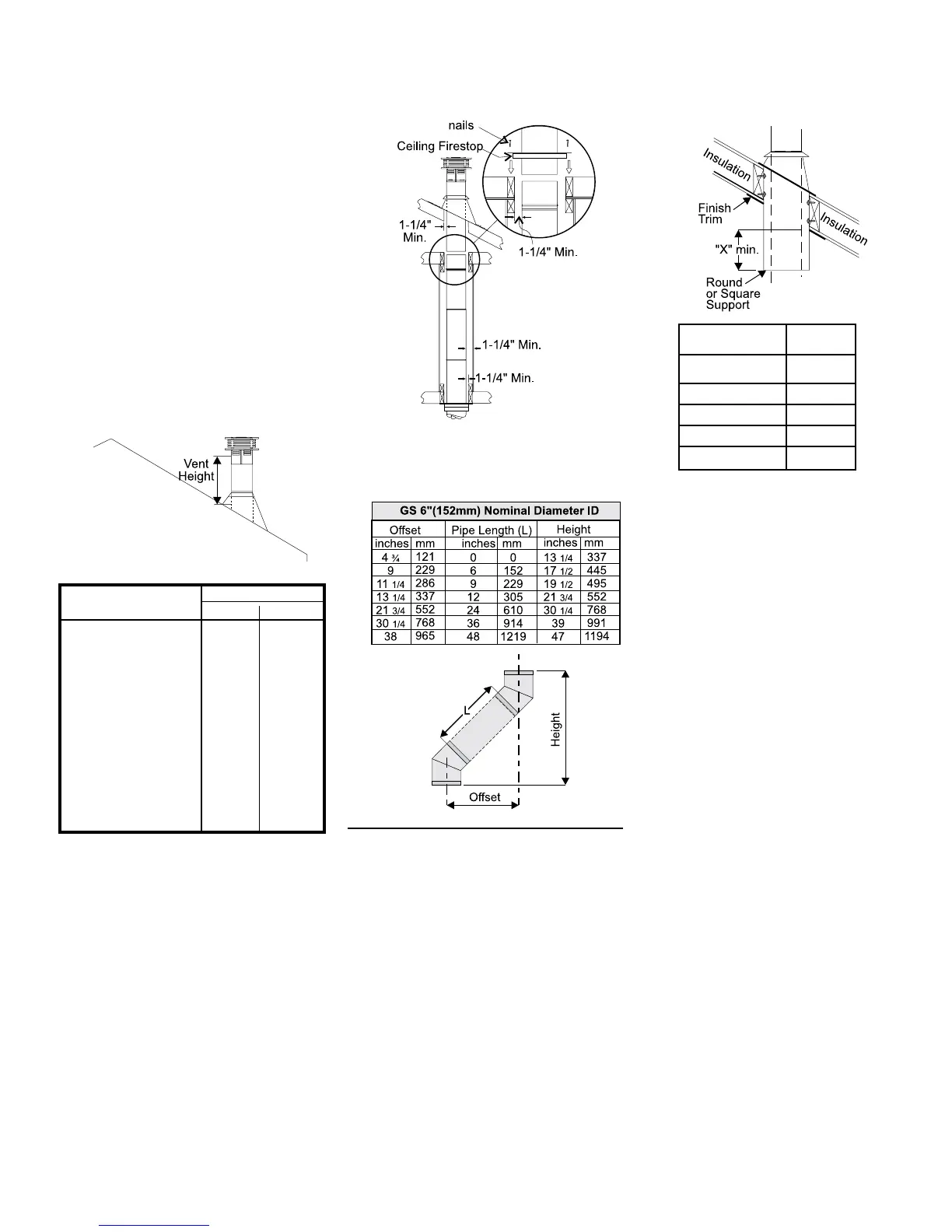
Offset Chart
Diagram 12
Diagram 13
Roof Pitch Minimum Vent Height
Feet Meters
at to 7/12 2 0.61
over 7/12 to 8/12 2 0.61
over 8/12 to 9/12 2 0.61
over 9/12 to 10/12 2.5 0.76
over 10/12 to 11/12 3.25 0.99
over 11/12 to 12/12 4 1.22
over 12/12 to 14/12 5 1.52
over 14/12 to 16/12 6 1.83
over 16/12 to 18/12 7 2.13
over 18/12 to 20/12 7.5 2.29
over 20/12 to 21/12 8 2.44
Galvanized pipe and elbows may be utilized
in the attic as well as above the rooine. The
galvanized nish is desirable above the rooine
due to its higher corrosion resistance.
Continue to add pipe sections through the
ashing until the height of the vent cap meets
the minimum height requirements specied
in diagram 12 or local codes. Note that for
steep roof pitches, the vertical height must be
increased. A poor draft, or down drafting can
result from high wind conditions near big trees
or adjoining roof lines, in these cases, increasing
the vent height may solve the problem.
7. Ensure vent is vertical and secure the base of
the ashing to the roof with roong rails, slide
storm collar over the pipe section and seal with
a mastic.
8. Install the vertical termination cap by twist lock-
ing it.
Notes:
a) For multistorey vertical installations, a Ceil-
ing Fire stop is required at the second oor,
and any subsequent oor. See diagram 13.
The opening should be framed to 10 " x 10"
inside dimensions, in the same manner as
shown in diagram 10.
b) Any occupied areas above the rst oor,
including closets and storage spaces,
through which the vertical vent passes,
must be enclosed.
Slope "X"
0/12 - 2/12 4"
2/12 - 7/12 5-1/2"
7/12 - 12/12 6-3/4"
12/12 - 24/12 7-1/2"
24/12+ 12-1/2"